Organic electroluminescent apparatus

Inactive Publication Date: 2009-10-22
SEIKO EPSON CORP
View PDF14 Cites 30 Cited by
  • Summary
  • Abstract
  • Description
  • Claims
  • Application Information

AI Technical Summary

Benefits of technology

[0027]This structure can increase th

Problems solved by technology

However, the formation of a dark spot has caused a deterioration in luminescence properties of organic EL elements.
However, when the capacity of the drying agent is exceeded, water remaining in the sealing component may react with the organic light-emitting layer, thus causing a dark spot or deterioration of the organic EL element.
Furthermore, when a region in which an organic light-emitting layer is formed includes a foreign substance, a back electrode may not fully cover the organic

Method used


Image

  • Organic electroluminescent apparatus
  • Organic electroluminescent apparatus
  • Organic electroluminescent apparatus

Examples


first embodiment

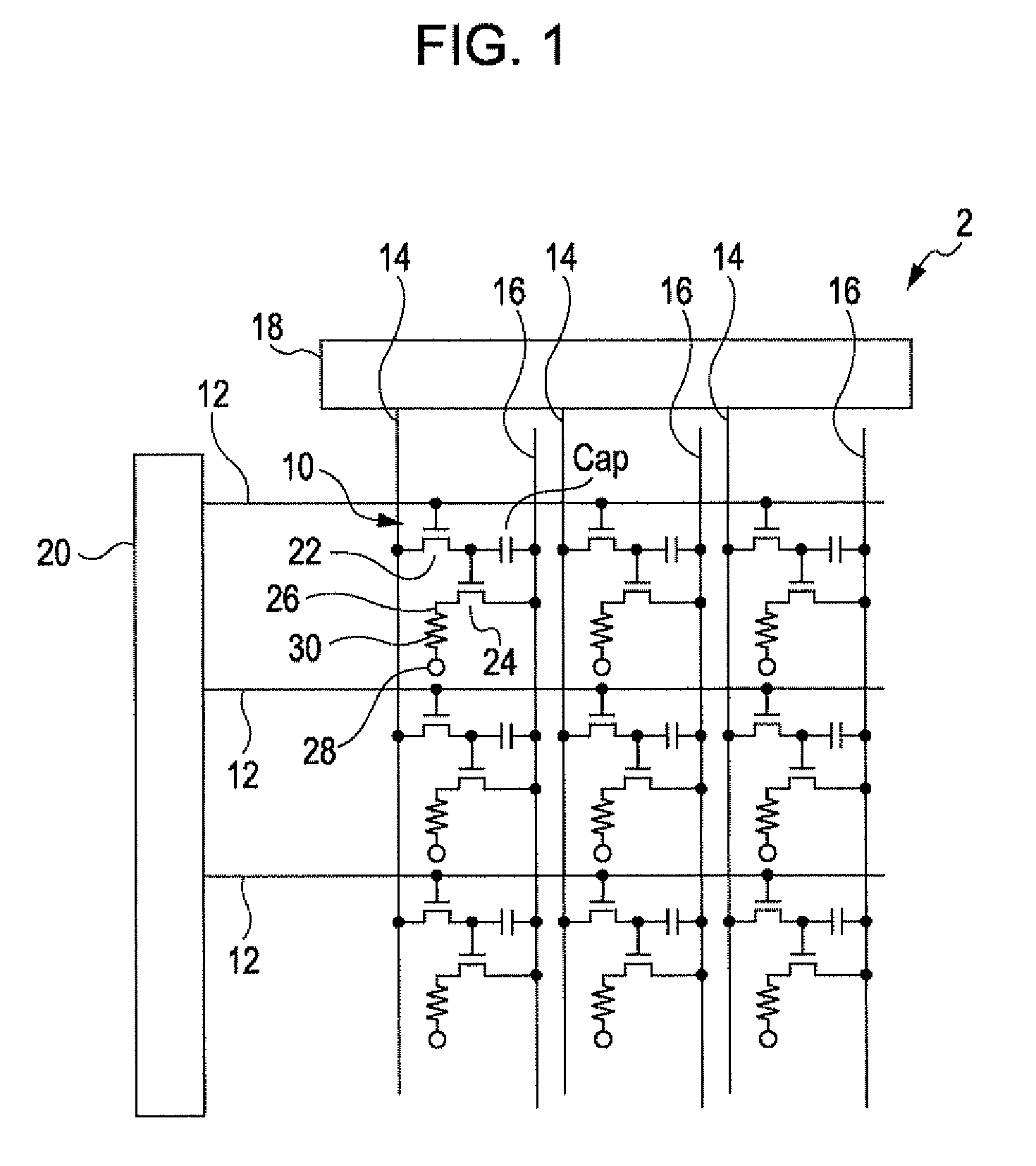
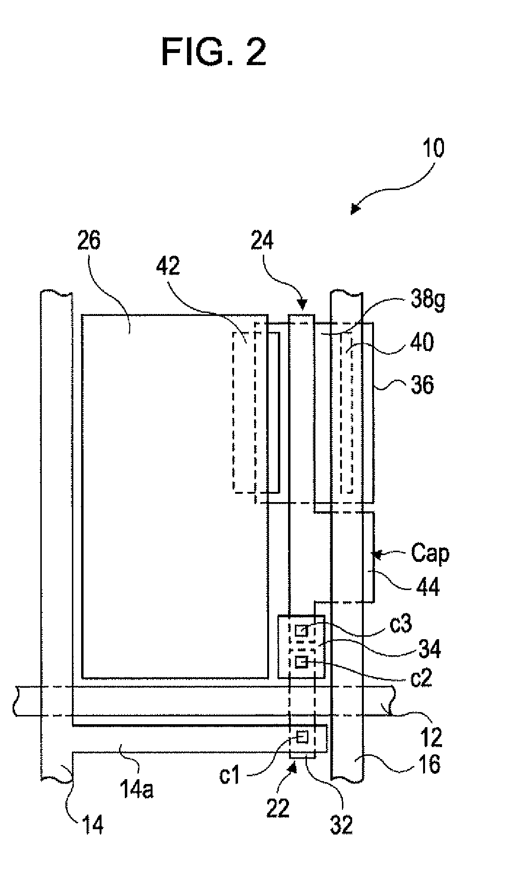
[0039]FIG. 1 is a circuit diagram of a matrix of pixel regions that constitute an organic EL light-emitting apparatus 2 according to a first embodiment. FIG. 2 is a plan view of a pixel 10 of the organic EL light-emitting apparatus 2. FIG. 3A is a plan view of the organic EL light-emitting apparatus 2. FIG. 3B is a cross-sectional view of the organic EL light-emitting apparatus 2 taken along the line IIIB-IIIB in FIG. 3A. In FIG. 3A, for the sake of clarity, a second substrate is eliminated.

[0040]As illustrated in FIG. 1, the organic EL light-emitting apparatus 2 includes a plurality of scanning lines 12, a plurality of signal lines 14, which intersect the scanning lines 12, a plurality of common feeders 16 parallel to the signal lines 14, and pixels 10 at the points of intersection of the scanning lines 12 and the signal lines 14.

[0041]The signal lines 14 are connected to a data drive circuit 18, which includes a shift register, a level shifter, a video line, and an analog switch. ...

second embodiment

[0114]A second embodiment will be described below with reference to the drawings.

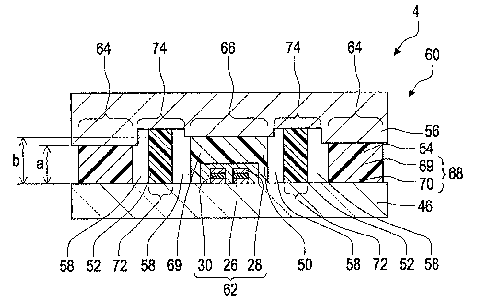
[0115]FIG. 5A is a plan view of an organic EL light-emitting apparatus 4 according to the second embodiment. FIG. 5B is a cross-sectional view of the organic EL light-emitting apparatus 4 taken along the line VB-VB in FIG. 5A. The organic EL light-emitting apparatus 4 has the same basic structure as the organic EL light-emitting apparatus 2 according to the first embodiment, except that a counter substrate 56 has a depression (recessed portion) 74, and that the thickness a of a first sealing portion 54 is different from the thickness b of a second sealing portion 50. Thus, the same components used in the present embodiment as in the first embodiment are denoted by the same reference numerals and will not be further described.

[0116]As illustrated in FIG. 5, the organic EL light-emitting apparatus 4 according to the present embodiment has the depression 74 in the counter substrate 56 corresponding to a re...

third embodiment

[0118]A third embodiment will be described below with reference to the drawings.

[0119]FIG. 6A is a plan view of an organic EL light-emitting apparatus 6 according to the third embodiment. FIG. 6B is a cross-sectional view of the organic EL light-emitting apparatus 6 taken along the line VIB-VIB in FIG. 6A. In FIG. 6A, for the sake of clarity, a counter substrate is eliminated. The organic EL light-emitting apparatus 6 has the same basic structure as the organic EL light-emitting apparatus 2 according to the first embodiment, except that a first sealing portion 54 is in contact with a second sealing portion 50. Thus, the same components used in the present embodiment as in the first embodiment are denoted by the same reference numerals and will not be further described.

[0120]In the organic EL light-emitting apparatus 6 according to the present embodiment, as illustrated in FIG. 6, a sealant 68 applied to a region 64 in which a first sealing portion is to be formed is in contact with ...


PUM


Abstract

An organic electroluminescent apparatus includes a first substrate and a second substrate facing each other, a first sealing portion that seals the first and second substrates so as to form a closed space between the first and second substrates, an organic light-emitting element that is disposed on the first substrate in the closed space and includes an organic light-emitting layer mainly composed of an organic light-emitting material, a second sealing portion that is disposed on the organic light-emitting element and seals the organic light-emitting element, and a drying agent film that is formed in a region surrounded by the first and second sealing portions and is mainly composed of a drying agent.

Description

BACKGROUND[0001]1. Technical Field[0002]The present invention relates to an organic electroluminescent apparatus.[0003]2. Related Art[0004]In recent years, organic electroluminescent apparatuses (organic EL apparatuses) that include light-emitting elements, such as organic electroluminescent elements (organic EL elements), on a substrate have been widely used as display apparatuses and as exposure units in electrophotographic image forming apparatuses[0005]Such organic EL apparatuses must be durable in long-term emission. However, the formation of a dark spot has caused a deterioration in luminescence properties of organic EL elements. In an organic EL element in which a transparent electrode, an organic light-emitting layer that includes a light-emitting layer composed of an organic compound, and a back electrode are sequentially layered, a dark spot is formed when water adsorbed on the surface of a component of the organic EL element or an ambient gas, such as water (moisture) or ...

Claims


Application Information

Patent Timeline
IPC IPC(8): H01J1/63
CPCH01L51/5237H10K50/846H10K50/8428H10K50/8426
Inventor NIMURA, TORUUCHIDA, MASAHIRO
Owner SEIKO EPSON CORP
Why Eureka
Try Eureka