Rotor type aircraft self-adaptive landing deck control system and rotor type aircraft self-adaptive landing deck control method

A control system and self-adaptive technology, applied to aircraft parts, motor vehicles, aircraft, etc., can solve problems such as high precision and high precision of difficult to control mechanical structures, system dynamic response speed that cannot meet the requirements, and general motion reduction effects, etc. , to achieve the effect of novel structure, strong anti-interference ability and heavy load

Active Publication Date: 2020-07-10
NANJING UNIV OF AERONAUTICS & ASTRONAUTICS +1
View PDF6 Cites 1 Cited by
  • Summary
  • Abstract
  • Description
  • Claims
  • Application Information

AI Technical Summary

Problems solved by technology

[0004] This kind of stable platform with two-axis structure is driven by a servo motor. Since there is a single point of force between the support frame and the platform, once the load mass on the platform is large or the mass distribution is uneven, the entire mechanism will be affected by the frame mass. Factors such as unbalanced torque, frictional interference torque between shafts, and mechanical structure resonance are seriously affected, as well as random errors and noises of the gyroscope, which are important reasons that affect the inertial stability accuracy of the system. In addition to the difficulty in controlling the high precision of the mechanical structure and machining In addition to the high precision of the installation, it is also difficult to improve the dynamic and static stability performance indicators of the system through effective control strategies. The reason is that the dual-axis servo motor has a general effect on reducing the motion of the carrier (hull) itself, and the dynamic response speed of the system is up to It does not meet the requirements, and the actual application effect is mediocre. This structure is generally only used in scenes where the base is a fixed still life. It is difficult to use this structure on ships.

Method used


Image

  • Rotor type aircraft self-adaptive landing deck control system and rotor type aircraft self-adaptive landing deck control method
  • Rotor type aircraft self-adaptive landing deck control system and rotor type aircraft self-adaptive landing deck control method
  • Rotor type aircraft self-adaptive landing deck control system and rotor type aircraft self-adaptive landing deck control method

Examples


Embodiment Construction

[0034] Embodiments of the present invention are described in detail below, examples of which are shown in the drawings, wherein the same or similar reference numerals denote the same or similar elements or elements having the same or similar functions throughout. The embodiments described below by referring to the figures are exemplary only for explaining the present invention and should not be construed as limiting the present invention.

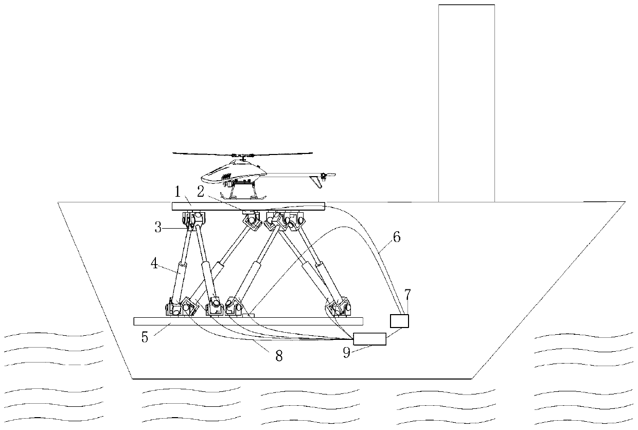
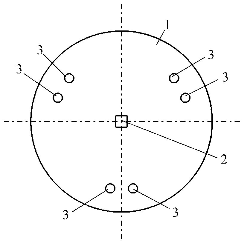
[0035] Such as figure 2 As shown, the present invention provides a landing deck system for an adaptive rotorcraft, including a landing deck 1, a MEMS gyroscope 2, a Hooke hinge 3, a hydraulic control valve 4, a base 5, a data line 6, an ECU control center 7, and a signal Line 8, hydraulic controller 9. Such as image 3 As shown, six Hooke hinges 3 are installed on the bottom surface of the landing deck 1, and the six Hooke hinges 3 are divided into three groups and evenly distributed on a circle with the center of the landing deck 1 as t...


PUM


Abstract

The invention discloses a rotor type aircraft self-adaptive landing deck control system and method. The system comprises a base, a landing deck, MEMS gyroscopes, hooke joints, a hydraulic control valve, an ECU control center and a hydraulic controller. And three groups of hooke joints are uniformly distributed on the bottom surface of the landing deck along the circumference. Three groups of hookejoints are uniformly distributed on the upper surface of the base along the circumference. The base is installed on a ship body. The hooke joint arranged on the landing deck and the base are staggered. The top ends of push rods of the hydraulic valves are connected with the landing deck through the hooke joints, and the bottom ends are connected with the base through the hooke joints. And the twoMEMS gyroscopes are respectively arranged on the landing deck and the base. When an aircraft lands on the carrier, signals of the MEMS gyroscopes are transmitted to the ECU control center, the control center transmits instructions to the hydraulic controller after calculation, the hydraulic controller sends the instructions to the hydraulic valves and adjusts the lengths of push rods of the hydraulic valves, so that the landing deck is kept horizontal all the time, is higher than the ship deck after rising and keeps the altitude unchanged. The system is stable in performance and high in control precision.

Description

technical field [0001] The invention relates to an adaptive landing deck control system and method of a rotorcraft, and belongs to the technical field of horizontal stability of the landing deck of a rotorcraft on a small and medium carrier. Background technique [0002] In recent years, with the development of the UAV market, rotor UAVs have quickly gained the attention and love of a large number of consumer groups due to their excellent control performance and the convenience of vertical take-off and landing. At present, the application of land-based rotor UAVs has been very extensive, but there are not many applications of ship-borne rotor UAVs. The main reason is that it is very difficult for rotor UAVs to land on shaking ships. The ship is affected by the waves, resulting in uncontrollable attitude, overturning, skidding and other unsuccessful landings, resulting in aircraft crashes or ship damage, casualties and other major accidents on board. Therefore, how to allow ...

Claims


Application Information

Patent Timeline
Patent Type & Authority Applications(China)
IPC IPC(8): B64F1/00
CPCB64F1/00B64U10/10B64U70/00
Inventor 周福亮聂宏魏小辉汤为伟丁林
Owner NANJING UNIV OF AERONAUTICS & ASTRONAUTICS
Why Eureka
Try Eureka