Rotating electric machine

a rotating electric machine and rotating shaft technology, applied in the direction of dynamo-electric machines, electrical devices, windings, etc., can solve the problems of delayed fracture and sudden brittle fracture of high-strength materials, the structure of related arts cannot easily ensure the strength reliability of bolts, and the failure to reduce initiation stress, so as to improve the reliability of bolt 10 joints, reduce centrifugal force, and lighten the coil support structure

Active Publication Date: 2018-10-09
HITACHI IND PROD LTD
View PDF24 Cites 1 Cited by
  • Summary
  • Abstract
  • Description
  • Claims
  • Application Information

AI Technical Summary

Benefits of technology

[0009]When the weight is loaded to bolt 10 fastener, the excessive load is determined by ratio of the stiffness of the bolt 10 and fastened member. The ratio is generally defined in coefficient of internal force. As shown in FIG. 5, the structure described in JP2002-58188 can't easily ensure the stiffness as fastened member because the hole is formed directly under the bottom of the bolt 10 fastener. And the load against the bolt 10 is big on the fastened member. Reducing centrifugal force by downsizing and lightening ends up increasing the loaded weight of the bolt 10.
[0011]Thus the above related art can't solute the problem to speed up the rotating electric machine. To solve the above-described problems, it is needed to reduce the centrifugal force by downsize and lighten the coil support structure and to reduce loads applied to bolt 10 by ensuring the stiffness of the structure. One aspect of the inventive coil support structure and electric rotating machine are to solve this problem and to provide high reliable rotating electric machine.
[0013]According to the inventive coil support structure and the electric rotation machine, it is possible to reduce centrifugal force by downsize and lighten the coil support structure and to ensure the stiffness around the bolt 10 joints of the coil support structure. And it is possible to improve the reliability of the bolt 10 joints by reducing load applied to bolt 10s to realize high speed rotating electric machine.

Problems solved by technology

However, the structure of related arts can't easily ensure the strength reliability of the bolt 10 fastener for speeding up the rotating electric machine.
If a high strength material is used, it is not easy to reduce initiation stress because bolt axis cross-section area is not enough to bear the centrifugal force.
And it is possible to cause the delayed fracture and suddenly brittle fracture for high strength material.
Thus the above related art can't solute the problem to speed up the rotating electric machine.

Method used


Image

  • Rotating electric machine
  • Rotating electric machine
  • Rotating electric machine

Examples


Embodiment Construction

[0033]One or more inventive electrical rotating machine and coil support structure will be described in using figures. This electrical rotating machine includes a salient-pole rotor, its configuration will be described below.

[0034]First, a synchronous machine, one of the electric machines, will be described. Synchronous machine include two types, one being the revolving-armature type, and the other the revolving-field type.

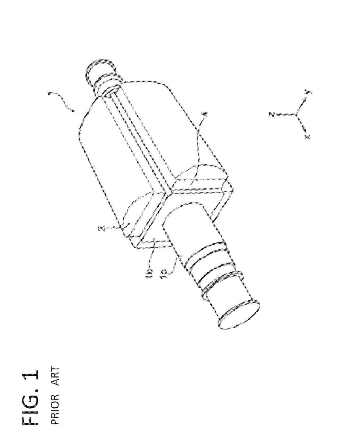
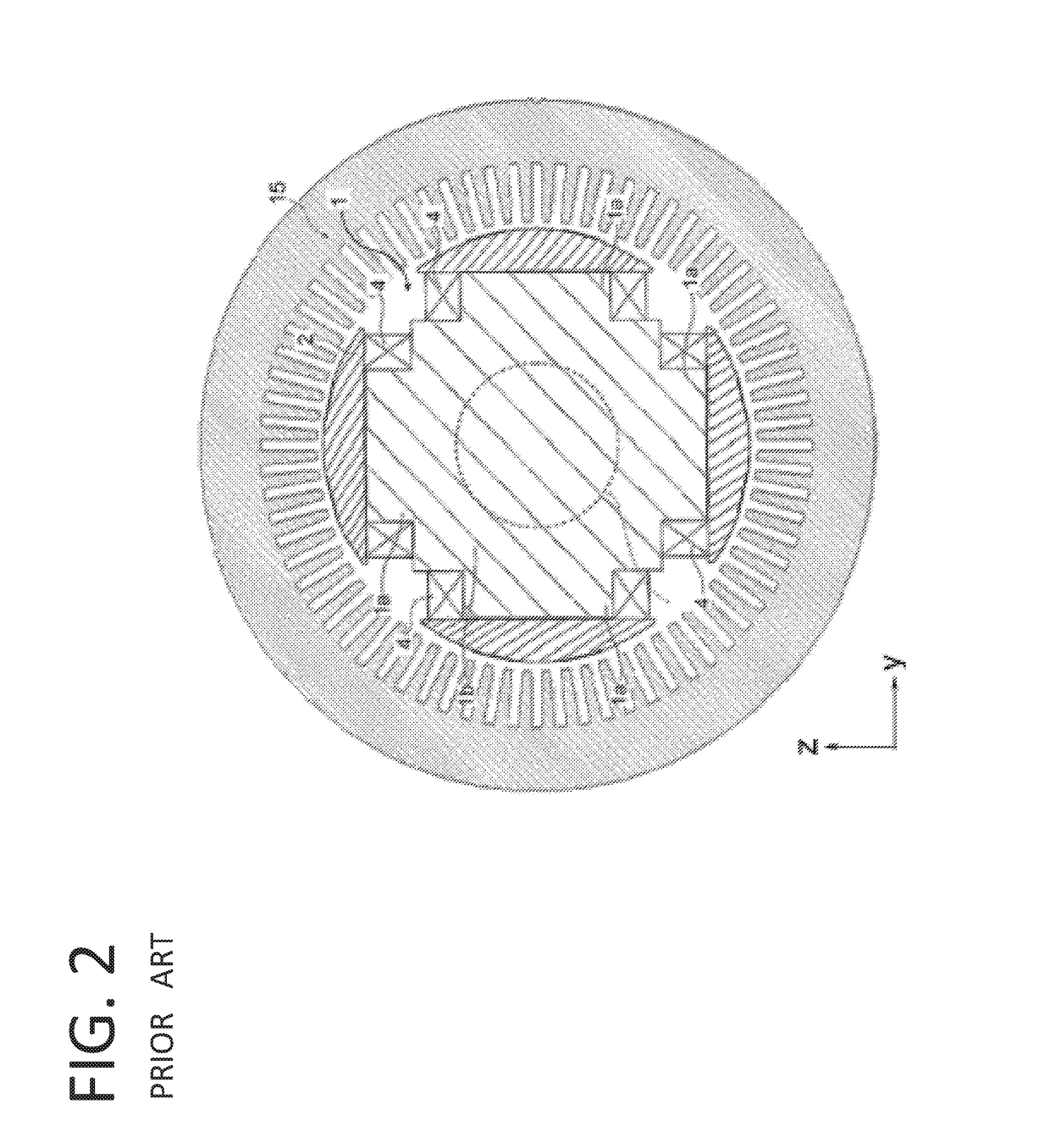
[0035]FIG. 1 is a perspective view of the revolving-field type rotor 1, as an example, a case in which four magnetic field poles are formed. FIG. 2 is a rotating axis cross-sectional view of the revolving-field type rotor 1. As depicted in FIG. 2, tip ends of the respective magnetic field poles outwardly project as many as the number of the magnetic field poles are collectively called “salient-pole rotors”. Stator 15 is formed outer side of the rotor 1 and rotor 1 is included in the stator 15.

[0036]A pole body 1a is formed on a central part of the shaft 1c, and th...


PUM


Abstract

A coil support structure including a coil spacer, a yoke spacer, and a support formed between the coil spacer and the yoke spacer. And the support has laterally protruding parts.

Description

CROSS-REFERENCE TO RELATED APPLICATION[0001]This application claims the priority of PCT Patent Application PCT / JP2015 / 063707 filed May 13, 2015.BACKGROUND OF THE INVENTION[0002]This inventive electrical rotating machine includes conventionally-known salient-pole rotor and a synchronous machine. A synchronous machine can control power factor by adjusting excitation so that operate in power factor of 1.0 or leading power factor. So a synchronous machine is widely used as a driving source of high capacity compressor and pump in plant system. Synchronous machine include two types, one being the revolving-armature type, and the other the revolving-field type. The revolving-field type is used as a driving force in high capacity machine in most cases.[0003]FIG. 1 is a perspective view of the revolving-field type machine 1 in case of four magnetic field poles. FIG. 2 is a cross-sectional view of the revolving-field type machine. As predicted FIG. 2, the rotor 1 that have the tip ends of the...

Claims


Application Information

Patent Timeline
Patent Type & Authority Patents(United States)
IPC IPC(8): H02K3/32H02K3/51H02K3/52
CPCH02K3/32H02K3/527H02K3/51
Inventor IMURA, MAKOTOKOYAMA, TAKAYUKINAKAE, SHIGEKIIIZUKA, MOTONOBUMATSUMOTO, MASANORIOOTAKA, HIDEYUKI
Owner HITACHI IND PROD LTD
Why Eureka
Try Eureka