

Heat regulating device for an integrated circuit
- Summary
- Abstract
- Description
- Claims
- Application Information
AI Technical Summary
Benefits of technology
Problems solved by technology
Method used
Image

Examples
Embodiment Construction
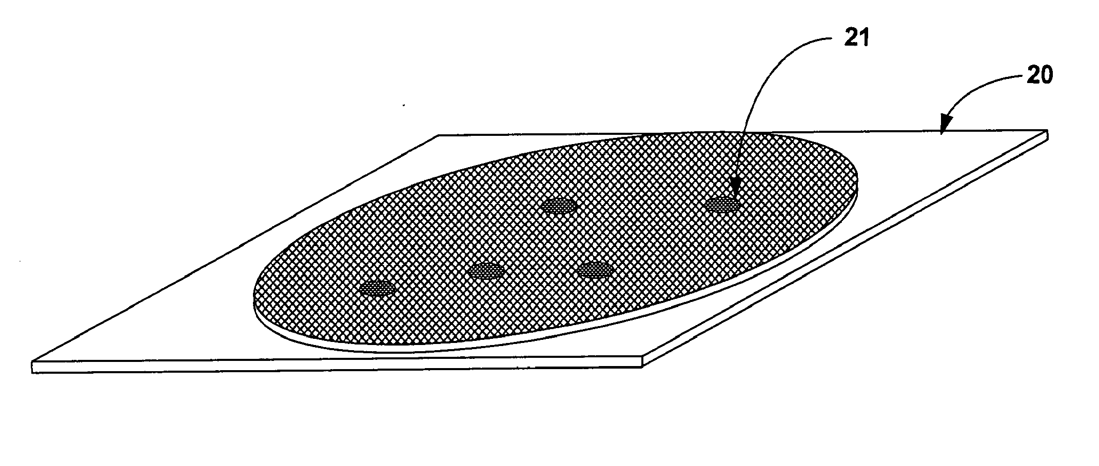
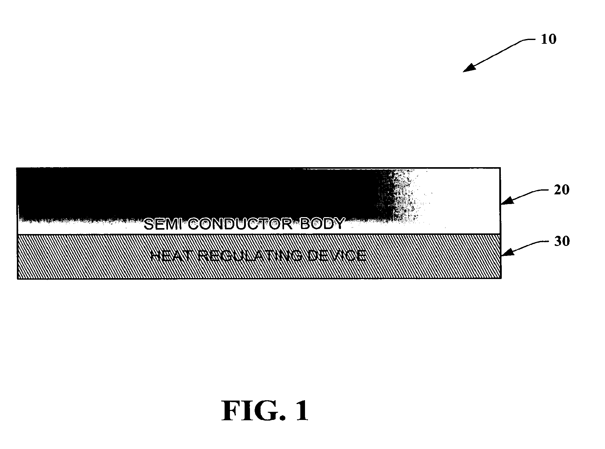
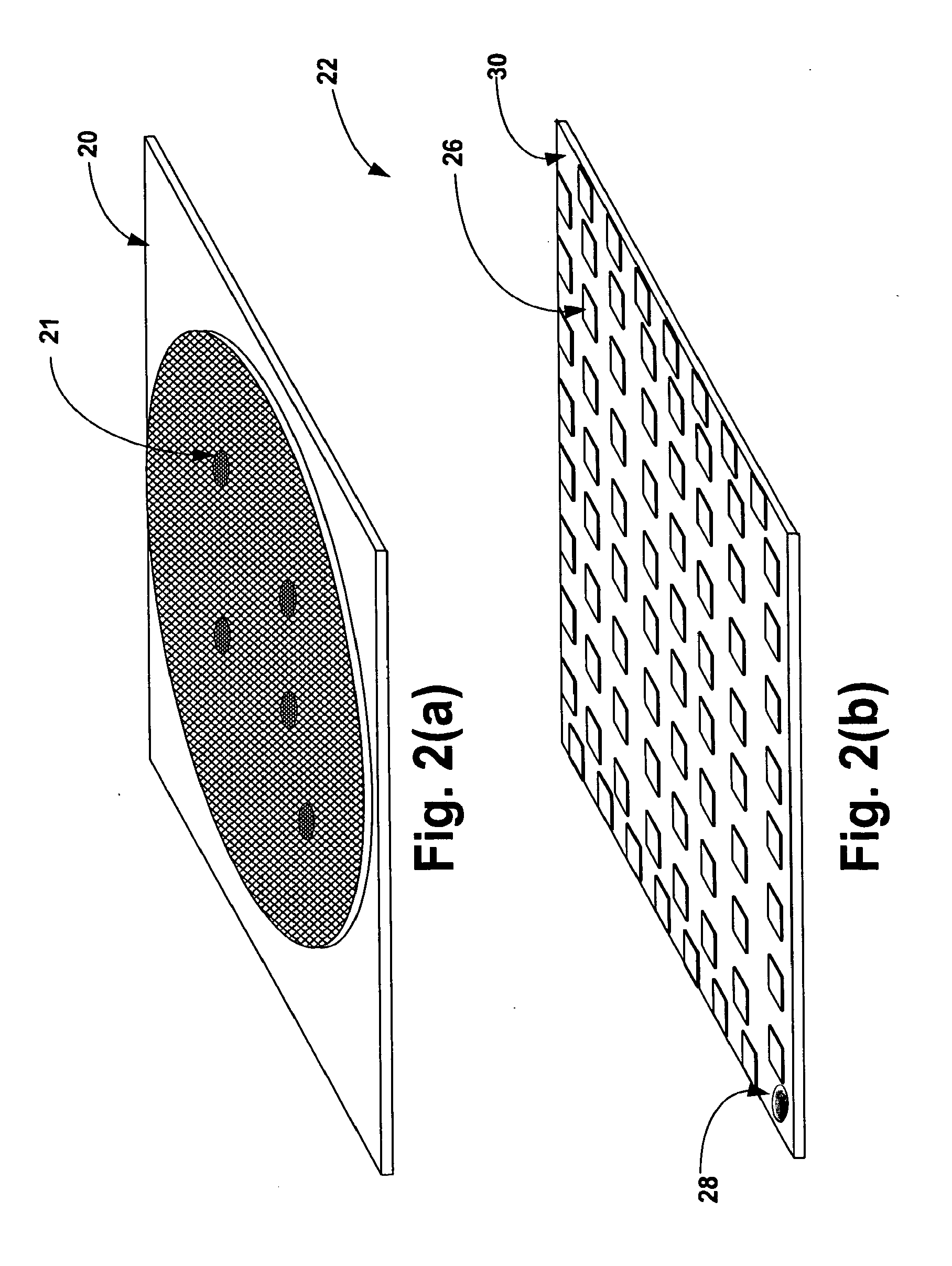
[0029]The various aspects of the present invention will now be described with reference to the drawings. The invention provides a system and methodology for regulating and monitoring heat dissipation of a semiconductor device, by employing an assembly of thermo-electrical structures that in part form a heat regulating device.
[0030]As used in this application, the term “computer component” or “system” is intended to refer to a computer-related entity, either hardware, a combination of hardware and software, software, or software in execution. For example, a computer component may be, but is not limited to being, a process running on a processor, a processor, an object, an executable, a thread of execution, a program, and / or a computer. By way of illustration, both an application running on a server and the server can be a computer component. One or more computer components may reside within a process and / or thread of execution and a component may be localized on one computer and / or d...
PUM
 Abstract
Description
Claims
Application Information