
Connector and infusion tube set

a technology of infusion tube and connector, which is applied in the direction of catheters, medical devices, other medical devices, etc., can solve the problems of not being able to unlock, etc., to achieve the effect of reliably recognizing that unlocking has occurred

Active Publication Date: 2010-02-04
TERUMO KK
View PDF1 Cites 13 Cited by
  • Summary
  • Abstract
  • Description
  • Claims
  • Application Information

AI Technical Summary

Benefits of technology

The present invention provides a connector and an infusion tube set that can reliably be unlocked and confirmed. The connector includes a male connector section, a female connector section, and a male lock section or a female lock section that can be coupled together. The male lock section or the female lock section can be coupled with another male lock section or female lock section to create a locked condition. The connector also includes a seal member that maintains liquid-tightness of the connection in the locked condition. The unlocking sound is generated when the locked condition is released. The connector is designed to ensure that unlocking can be recognized and confirmed. The invention also provides a method for unlocking the connector.

Problems solved by technology

Therefore, it is unknown whether unlocking has successfully been achieved or not, and there may be cases in which, for example, an operator thinks that he or she has completed the operation for unlocking the connection means once locked to each other, but where actually, unlocking has not been achieved.
In this situation, depending on the magnitude of the pulling forces, there is a risk that excessive forces might be exerted on the male lock section and the female lock section on respective sides, eventually breaking one or both of the lock sections.

Method used


Image

  • Connector and infusion tube set
  • Connector and infusion tube set
  • Connector and infusion tube set

Examples


Embodiment Construction

[0087]The connector and the infusion tube set according to the present invention will be described in detail below, based on a preferred embodiment thereof as shown in the accompanying drawings.

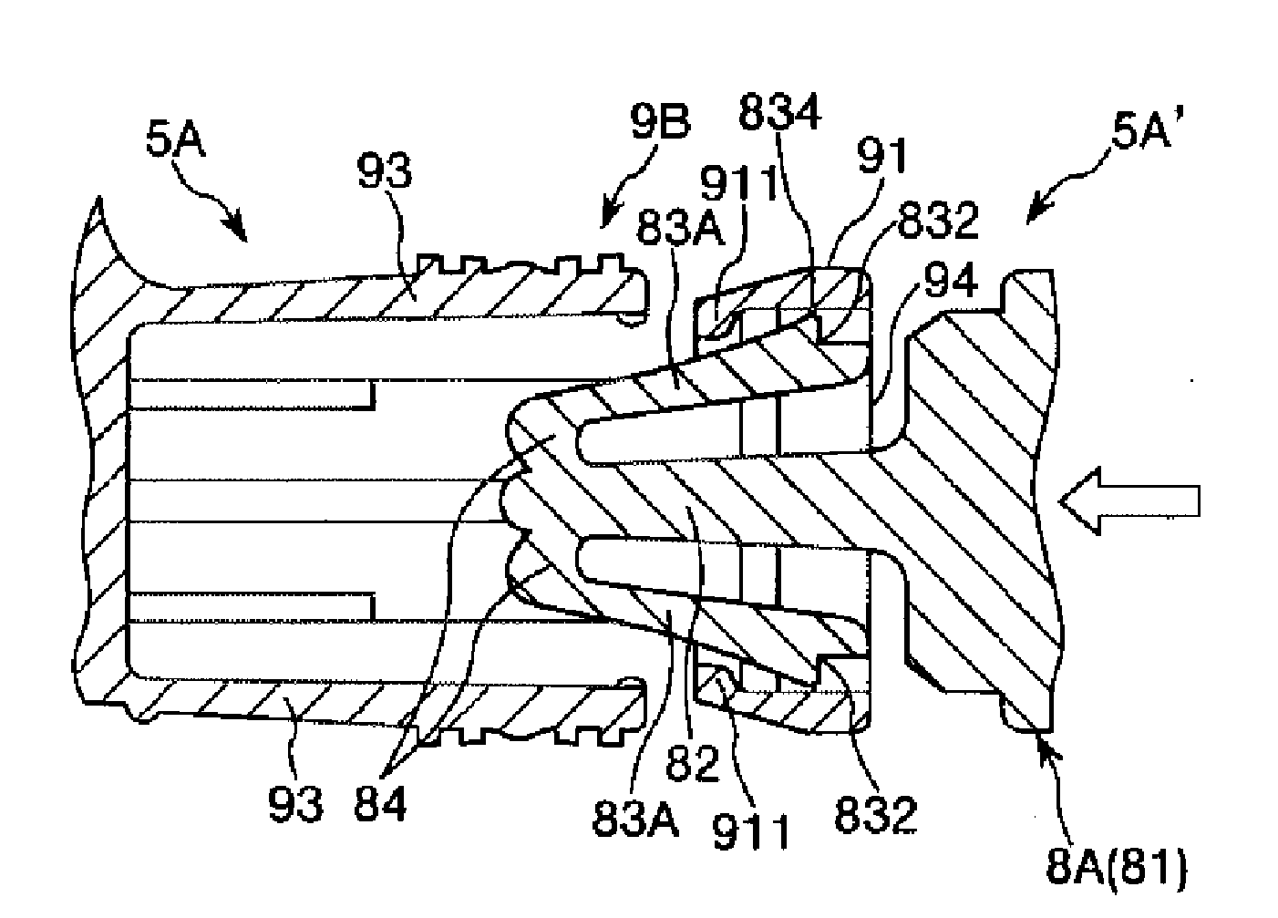
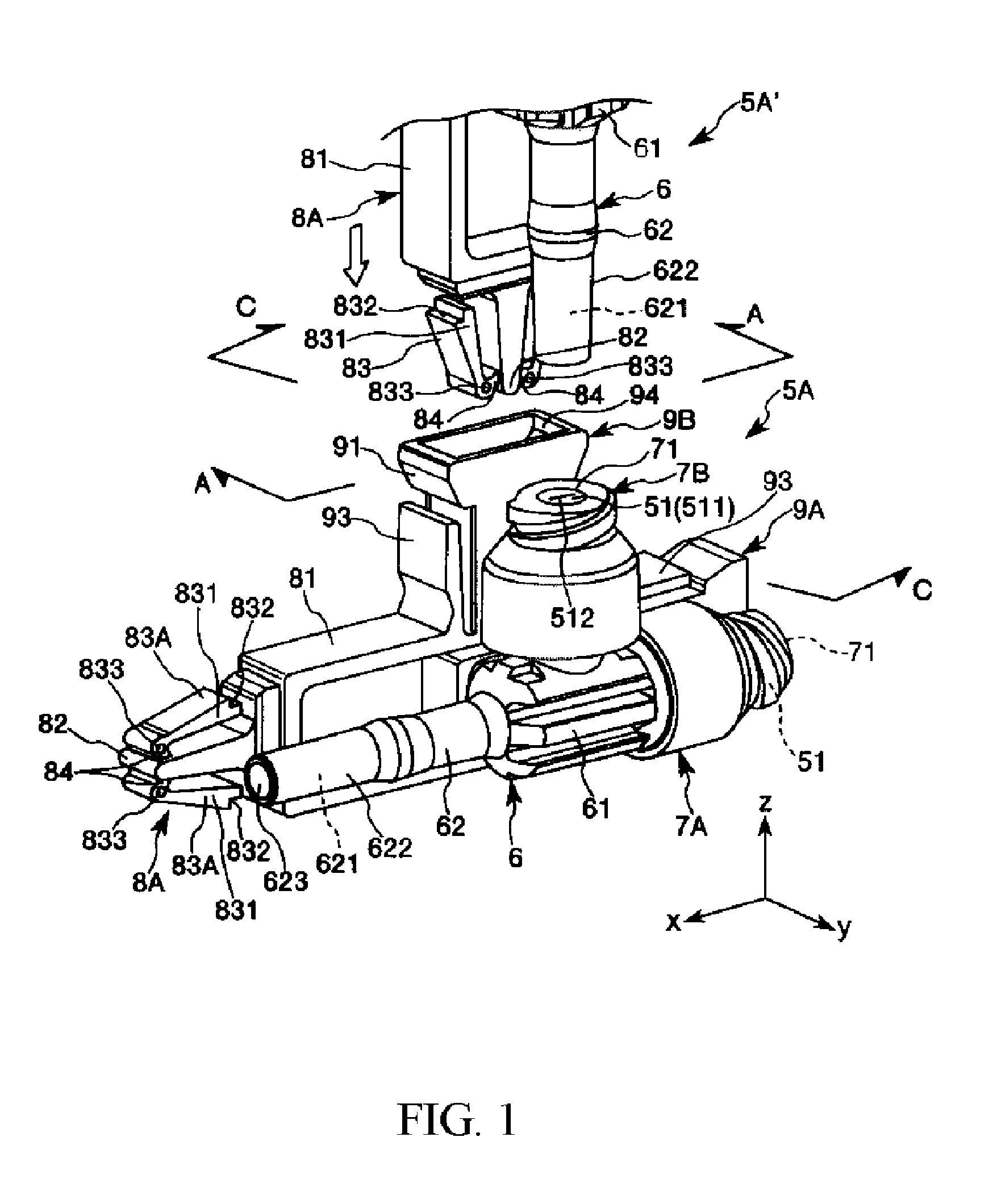
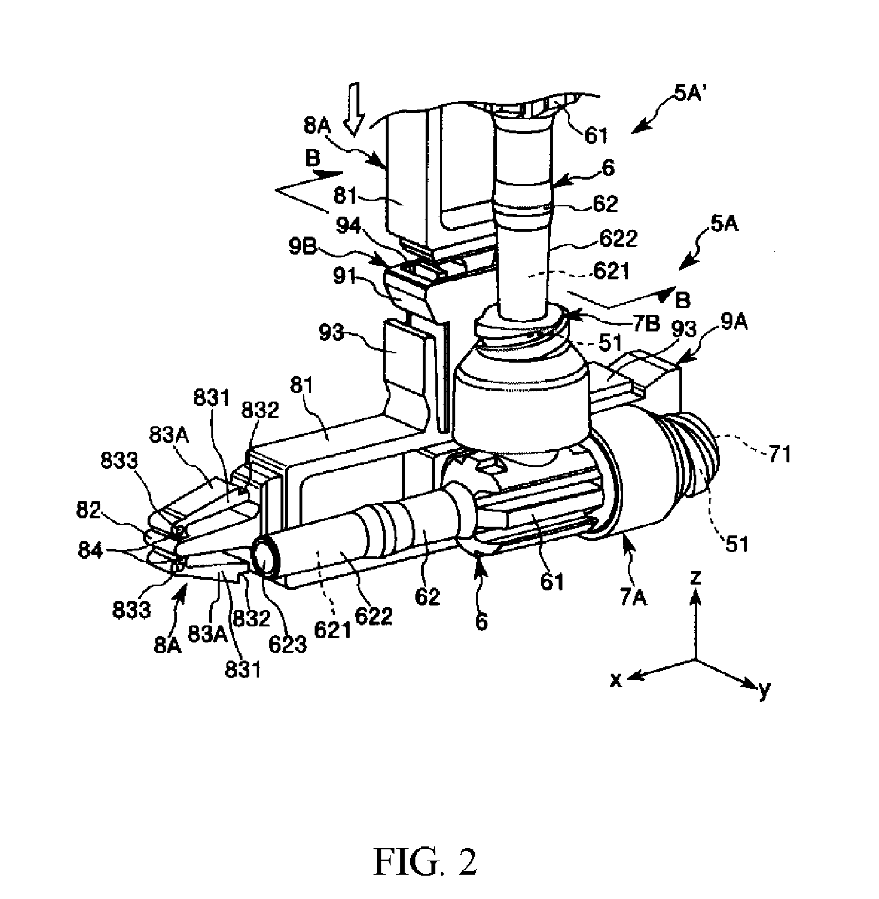
[0088]FIGS. 1 to 3 are perspective views respectively showing the connector according to the present invention; FIG. 4 illustrates sectional views taken along line A-A of FIG. 1; FIG. 5 is a partially enlarged detailed view of FIG. 4(b); FIG. 6 is a partially enlarged detailed view of FIG. 4(c); FIGS. 7 and 8 are partially enlarged detailed views (sectional views) sequentially illustrating an unlocked condition of the connector shown in FIG. 1; FIG. 9 illustrates sectional views taken along line B-B of FIG. 2; FIG. 10 is a perspective view showing a valve element (seal member) possessed by the connector shown in FIG. 1; FIG. 11 is a sectional view taken along line C-C of FIG. 1; FIG. 12 is a sectional view taken along line D-D of FIG. 3; FIG. 13 is a plan view of an infusion tube set accordin...


PUM


Abstract

A connector includes a male connector section having a cavity, a female connector section having a cavity to which another male connector section the same as the male connector section can be connected, a male lock section or a female lock section, disposed adjacent to the male connector section so that the connection direction thereof is parallel to that of the male connector section, a female lock section disposed adjacent to the female connector section so that the connection direction thereof is parallel to that of the female connector section, and to which another male lock section the same as the male lock section can be coupled, or a male lock section disposed adjacent to the female connector section so that the connection direction thereof is parallel to that of the female connector section, and to which another female lock section the same as the female lock section can be coupled, and a seal member formed from an elastic material, for maintaining liquid-tightness of the connection between the other male connector section and the female connector section in a locked condition where the other male lock section and the female lock section are coupled to each other, wherein an unlocking sound, which enables recognition of unlocking, is generated at a time of unlocking when the locked condition is released.

Description

TECHNICAL FIELD[0001]The present invention relates to a connector and an infusion tube set.BACKGROUND ART[0002]In medical appliances requiring connection of passages for liquid(s) to be used for infusion, transfusion, nutrient dosing or the like, the liquid passages (circuits) must be connected and disconnected as required, when sustainedly or momentarily causing a flow of the liquid(s), such as a liquid medicine, blood, and liquid food. In such a situation, it is known to attach a connection means for connecting the liquid passages to an intermediate portion of the circuit. Typical examples of the connection means include the one described in Patent Document 1.[0003]The connection means (connector) includes a male connector section, a female connector section, a male lock section, and a female lock section. When connection means having such a configuration are connected to each other, the male lock section on one side and the female lock section on the other side engage with each o...

Claims


Application Information

Patent Timeline
Patent Type & Authority Applications(United States)
IPC IPC(8): A61M39/10
CPCA61M39/1011A61M39/26A61M2205/581A61M2039/1033A61M2039/1027
Inventor HISHIKAWA, YOSHINORIYOKOTA, TAKAYUKI
Owner TERUMO KK
Learn More