Wireless video transmission device, wireless video reception device, wireless communication system, and cec message transmission method used therefor

Active Publication Date: 2010-03-18
MAXELL HLDG LTD
View PDF2 Cites 13 Cited by
  • Summary
  • Abstract
  • Description
  • Claims
  • Application Information

AI Technical Summary

Benefits of technology

[0017]In accordance with the configuration of the aforementioned present invention, there is the advantage that, by first fixing the physical address of the video transmission device, whether it be in the case where there is a variation in the configuration of the piece of video equipment connected by wire with the video reception device or the case where the video transmission destination is switched to a separate video reception device, the effort of collecting the physical address again can be eliminated, since the physical address of the video transmission device does not change and the transmission of the CEC message can be started rapidly.
[0018]Second, there is the advantage that, since it is possible to rapidly start transmission of the CEC message to the piece of AV equipment being the destination of the CEC message by transmitting by dividing up the wireless transmission units of the CEC message, it is possible for the destination AV equipment to quickly obtain the response result of the reception conf

Problems solved by technology

First, there is the point that time is required for the determination of the physical addresses of

Method used


Image

  • Wireless video transmission device, wireless video reception device, wireless communication system, and cec message transmission method used therefor
  • Wireless video transmission device, wireless video reception device, wireless communication system, and cec message transmission method used therefor
  • Wireless video transmission device, wireless video reception device, wireless communication system, and cec message transmission method used therefor

Examples


first embodiment

1. The First Embodiment

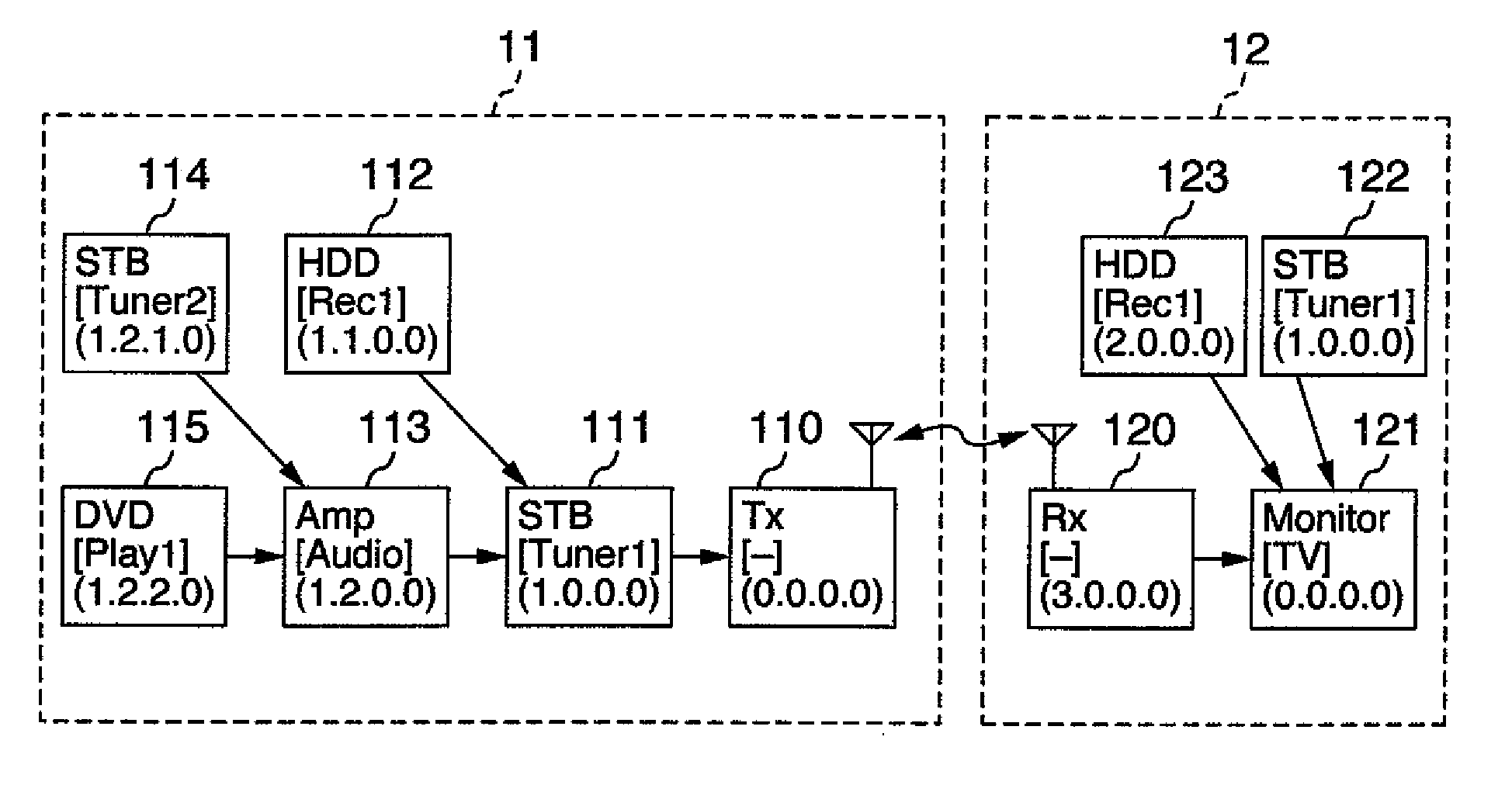
[0035]FIG. 1 is a block diagram showing the configuration of a system, connecting AV equipment by wire and wirelessly, which is the first embodiment associated with the present invention. In FIG. 1, a wireless video transmission device 110 and a wireless video reception device 120 correspond to a wireless communication system according to the embodiment of the present invention. The wireless video transmission system associated with the present embodiment has a first CEC system 11 and a second CEC system 12.

[0036]The first CEC system 11 is a CEC system on the side of wireless video transmission device 110, in which at least one piece of first AV equipment, e.g. an STB (111), an HDD recorder 112, an audio amplifier 113, an STB 114, and a DVD player 115, is connected by wire, with e.g. an HDMI cable. The arrows in the diagram indicate the transmission direction of the video frame signals connected by HDMI. The CEC messages have bi-directional transmission. The t...

second embodiment

2. The Second Embodiment

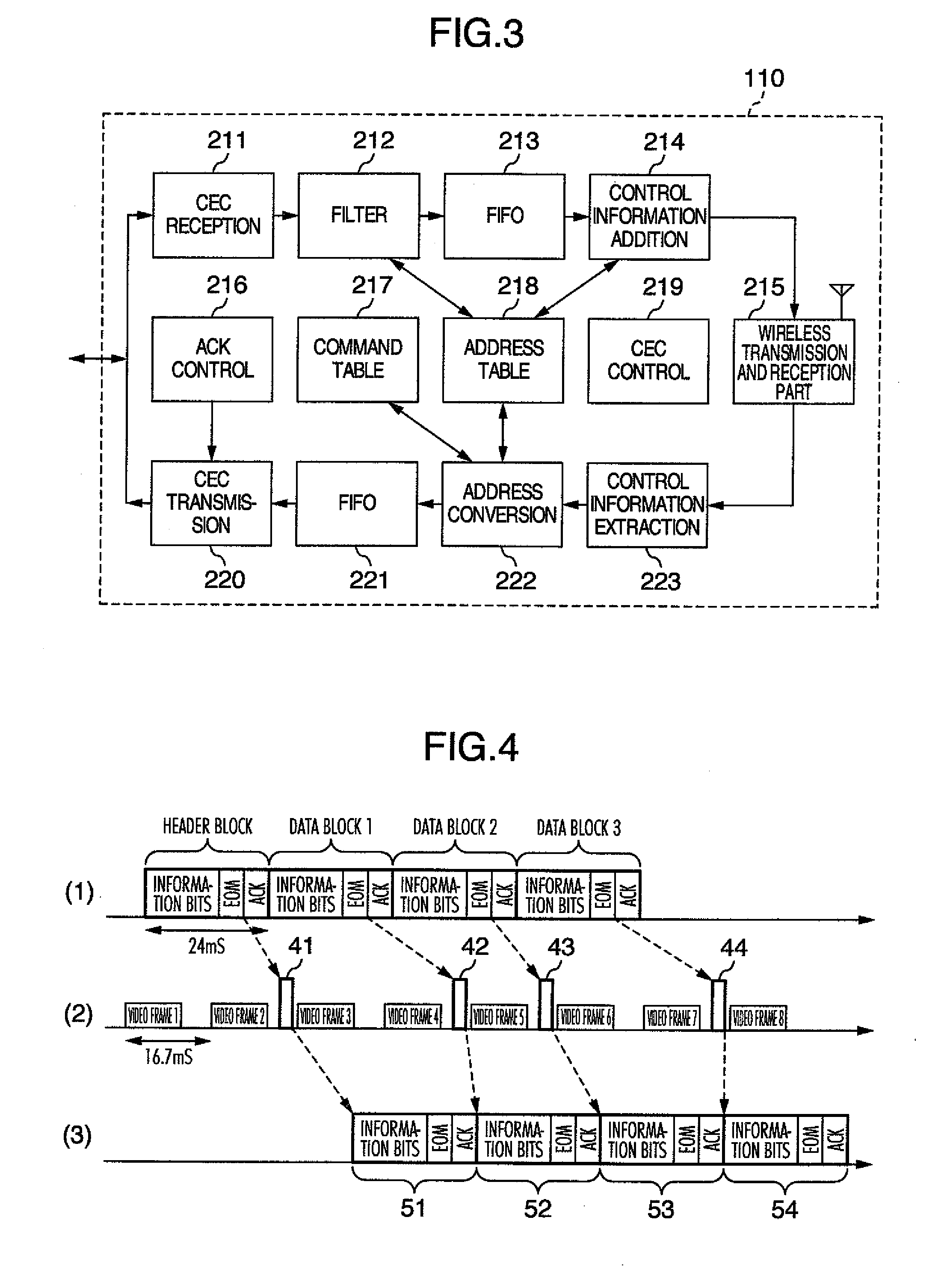
[0068]Next, an explanation of Embodiment 2 of the present invention will be given using the sequence diagrams of FIG. 6 and FIG. 7. Since the equipment configuration is the same as that of Embodiment 1, an explanation thereof is omitted. In Embodiment 2, by transmitting CEC messages wirelessly by dividing them up not in units of one byte but in bit units, the responsiveness of reception confirmation ACK bits is further improved, the data inside the information bit groups being expressed in bit units.

[0069]After reception of the previous information bits including at least the destination bits, header block 1 is transmitted as wireless packet 41 inserted in the vertical retrace interval. With wireless packet 45 of the following vertical retrace interval, the EOM bit of the header block and the D0 to D5 data bits of data block 1, received up to that point, are transmitted to wireless video reception device 120. As for header block 51 sent out by the wireless vi...

third embodiment

3. The Third Embodiment

[0071]Embodiment 3 of the present invention will be explained using FIG. 8. FIG. 8 is a block diagram showing the configuration of a system in which there are assumed pieces of AV equipment that are connected by wire with a wireless video reception device. Embodiment 1 was one in which a piece of AV equipment inside CEC system 11 is made to exist virtually inside the wireless video reception device in second CEC system 12. In FIG. 8, there is assumed a form where the equipment inside second CEC system 12 is connected directly with a wireless communication system 100 composed of wireless video reception device 120 and wireless video transmission device 110.

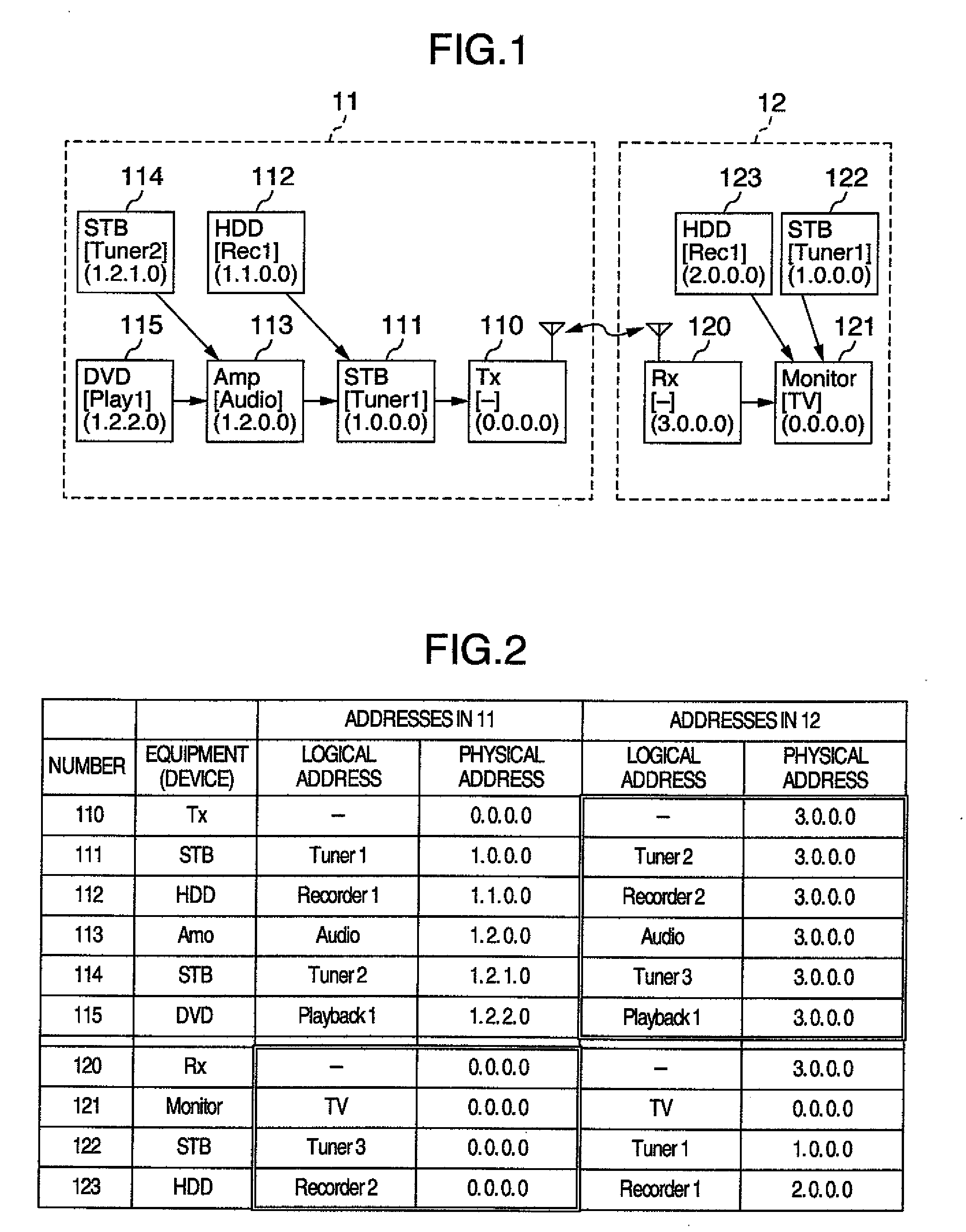
[0072]By treating the input terminal number as a logical address number and taking the second digit of the physical address to be the logical address, it is possible to simplify the conversion table. If simplification is not of concern, other ways are acceptable, such as allocating number in the order in whic...


PUM


Abstract

After fixing the physical address of a wireless video transmission device to a route address or the like, it is possible to shorten the switchover time by having a conversion table provided that maps the physical addresses on the wireless video reception device side, since it does not occur that the addresses of AV equipment connected by wire with the wireless video transmission device are changed, even if the physical address of the wireless video reception device changes. Further, by performing split transfer of the CEC messages, it is possible to carry out transmission of the CEC messages promptly and to suppress reception confirmation bits with respect to CEC messages for which there exists no destination.

Description

INCORPORATION BY REFERENCE[0001]The present application claims priority from Japanese application JP2008-235872 filed on Sep. 16, 2008 and the content of which is hereby incorporated by reference into this application.BACKGROUND OF THE INVENTION[0002]1. Field of the Invention[0003]The present invention pertains to technology for wirelessly transmitting messages, such as CEC (Consumer Electronics Control) defined by e.g. the HDMI (High-Definition Multimedia Interface) Specification, for controlling video equipment such as e.g. DVD (Digital Versatile Disc) players.[0004]2. Description of the Related Art[0005]Technology in which video frame signals are sent from a video transmission device to a video reception device and CEC messages determined by the HDMI Specification are communicated wirelessly, bi-directionally, between the video transmission device and the video reception device is disclosed in JP-B-4116071, JP-A-2008-153826, and JP-A-2008-153827. In JP-B-4116071, there is describ...

Claims


Application Information

Patent Timeline
IPC IPC(8): H04N7/173H04B1/04H04B1/06H04N5/44H04N21/436
CPCH04L61/20H04L29/12207H04L61/103H04L61/5038H04L2101/622H04L12/40
Inventor KABUTO, NOBUAKI
Owner MAXELL HLDG LTD
Why Eureka
Try Eureka