Imaging lens and imaging apparatus

a technology of imaging lens and imaging apparatus, which is applied in the direction of optics, instruments, optics, etc., can solve the problems of difficult to achieve a small, fast, and inexpensive imaging lens capable of meeting the requirements, and achieve the effect of small, fast, and inexpensive imaging lens, small and inexpensiv

Active Publication Date: 2010-04-29
FUJIFILM CORP
View PDF4 Cites 11 Cited by
  • Summary
  • Abstract
  • Description
  • Claims
  • Application Information

AI Technical Summary

Benefits of technology

[0026]According to the above-mentioned aspect of the invention, the imaging lens includes the first lens that has the negative power and includes the concave surface facing the image side, the second lens having the positive power, the stop, the third negative lens, which is the biconcave lens, the fourth lens having the positive power, and the fifth lens that has the positive power and includes the convex surface facing the image side. The first to fifth lenses are arranged in this order from the object side. When the focal length of the entire lens system is f, the thickness of the center of the first l

Problems solved by technology

However, in the optical system according to the related art, it is difficult to achi

Method used


Image

  • Imaging lens and imaging apparatus
  • Imaging lens and imaging apparatus
  • Imaging lens and imaging apparatus

Examples


example 1

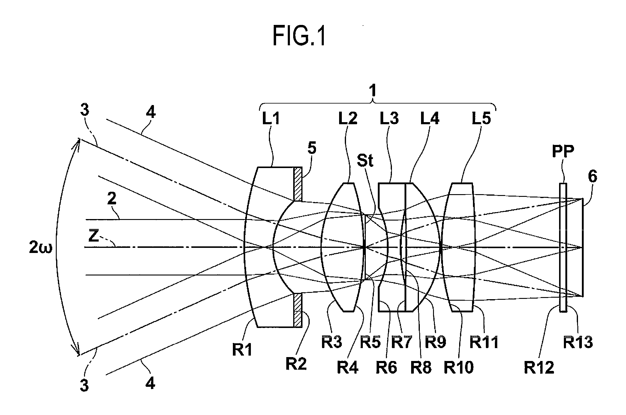
[0100]Lens data, various data, and expression data of an imaging lens according to Example 1 are shown in Table 1, and the structure of the imaging lens is shown in FIG. 2.

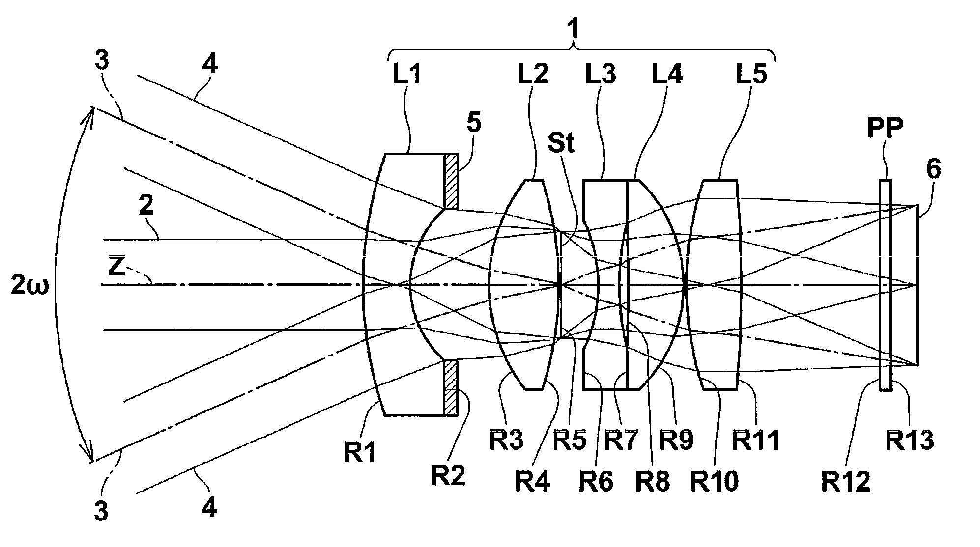
[0101]In the lens data shown in Table 1, the surface number of a component from the object side is represented as an i-th (i=1, 2, 3, . . . ) surface number. In this case, the surface of a component closest to the object side is given number 1, and the surface number is sequentially increased toward the image side. In addition, the lens data shown in Table 1 includes the aperture diaphragm St and the optical member PP.

[0102]In Table 1, Ri indicates the curvature radius of the i-th (i=1, 2, 3, . . . ) surface, and Di indicates the surface spacing between the i-th (i=1, 2, 3, . . . ) surface and an (i+1)-th surface on the optical axis Z. In addition, Ndj indicates the refractive index of a j-th (j=1, 2, 3, . . . ) optical component at the d-line. In this case, an optical component arranged closest to the object side...

example 2

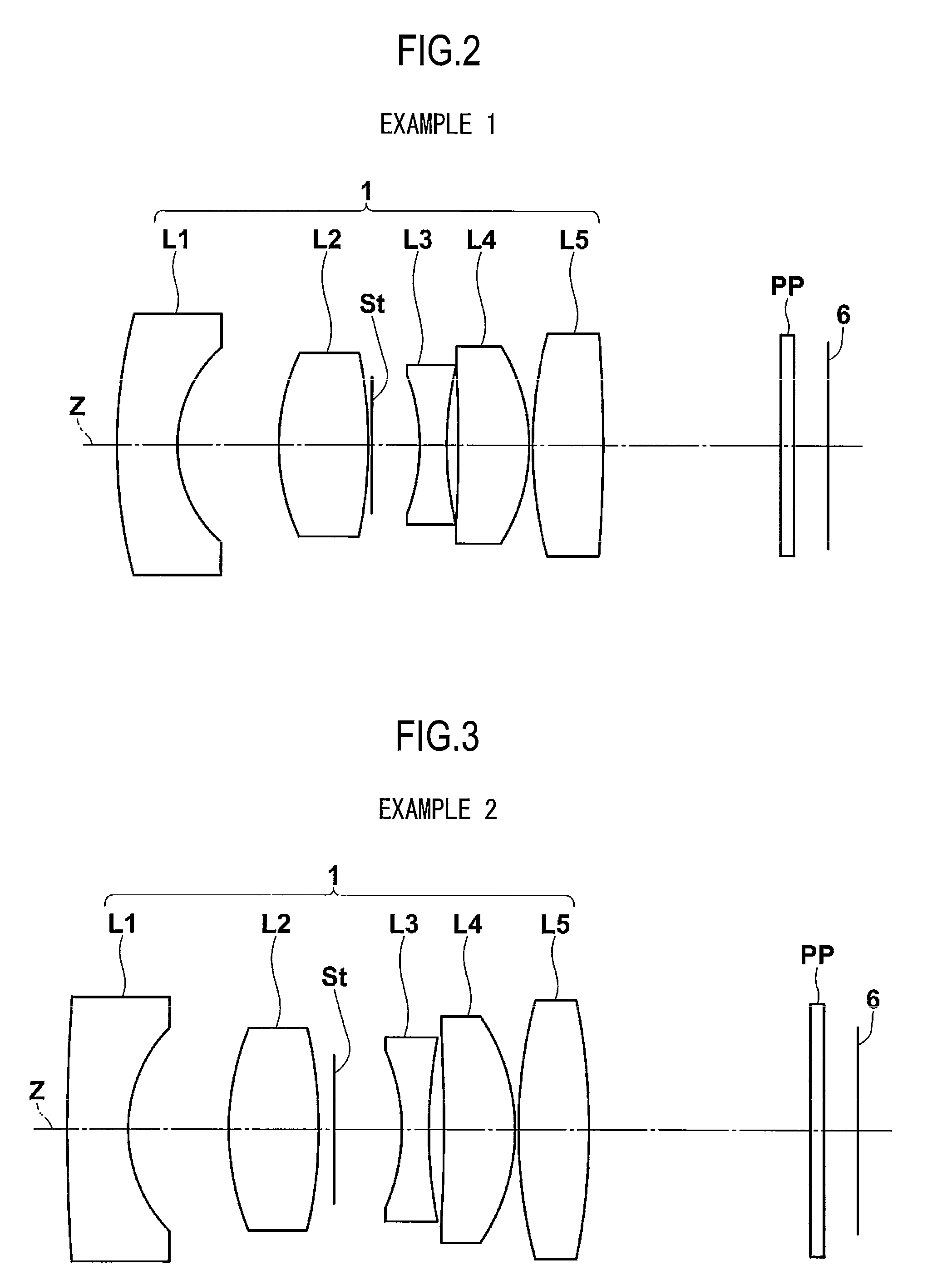
[0104]Lens data, various data, and expression data of an imaging lens according to Example 2 are shown in Table 2, and the structure of the imaging lens is shown in FIG. 3.

TABLE 2Lens DataRDNdγd156.371.801.516864.224.313.0038.012.671.834037.24−13.070.465(APERTURE∞2.00DIAPHRAGM)6−5.830.801.922918.9714.500.458−50.112.101.834842.79−6.030.101014.932.101.755052.311−19.500.5012∞0.401.516864.213∞7.0514(IMAGE∞0SURFACE)Various DataL(in Air)20.8Bf(in Air)6.4f7.02f129.16f1−9.13f23410.12f26.32f23458.15f3−4.42f34511.98f48.03f511.50

example 3

[0105]Lens data, various data, and expression data of an imaging lens according to Example 3 are shown in Table 3, and the structure of the imaging lens is shown in FIG. 4.

TABLE 3Lens DataRDNdγd111.541.501.589161.124.593.5036.232.551.834037.24−17.700.105(APERTURE∞1.42DIAPHRAGM)6−5.430.751.922918.9710.570.418−22.092.121.834842.79−5.370.201011.821.901.834842.711−30.085.8312∞0.401.516864.213∞0.2614(IMAGE∞0.00SURFACE)Various DataL(in Air)20.8Bf(in Air)6.4f7.04f127.13f1−14.06f23411.09f25.81f23457.50f3−3.80f34512.33f48.03f510.38


PUM


Abstract

An imaging lens includes, in order from an object side, a first lens having a negative power and including a concave image-side surface, a second lens having a positive power, a stop, a third negative lens, which is a biconcave lens, a fourth lens having a positive power, and a fifth lens having a positive power and including a convex image-side surface. The imaging lens satisfies the following conditional expressions:
0.18<(D4+D5)/f<0.44, and
0.18<D1/f
where f denotes a focal length of an entire lens system, D1 denotes a thickness of a center of the first lens, D4 denotes a distance from an image-side surface of the second lens to the stop on an optical axis, and D5 denotes a distance from the stop to an object-side surface of the third lens on the optical axis.

Description

CROSS-REFERENCE TO RELATED APPLICATIONS[0001]This application is based upon and claims the benefit of priority from the Japanese Patent Application No. 2008-277691 filed Oct. 29, 2008; the entire contents of which are incorporated herein by reference.BACKGROUND OF THE INVENTION[0002]1. Field of the Invention[0003]The present invention relates to an imaging lens used for an in-vehicle camera or a monitoring camera using an imaging device, such as a CCD or a CMOS, and more particularly, to an imaging lens used for an in-vehicle camera that captures the images of the front, side, and rear of a vehicle.[0004]2. Description of the Related Art[0005]In recent years, the size of an imaging device, such as a CCD or a CMOS, has been reduced, and the number of pixels thereof has increased. Therefore, it is necessary to reduce the size and weight of an imaging apparatus body and an imaging lens provided therein. Meanwhile, for example, in-vehicle cameras or monitoring cameras require a high-per...

Claims


Application Information

Patent Timeline
IPC IPC(8): G02B9/60
CPCG02B9/60
Inventor KITAHARA, YUYAMAMOTO, YOKOASAMI, TARO
Owner FUJIFILM CORP
Why Eureka
Try Eureka