
Keel mechanism for sailboats

a technology of keel mechanism and sailboat, which is applied in the direction of special-purpose vessels, floating buildings, transportation and packaging, etc., can solve the problems of preventing the boat from moving as fast as desired, assuming a position, and achieving stable and speedy sailboats

Inactive Publication Date: 2010-05-13
AMGEN FREMONT INC
View PDF10 Cites 6 Cited by
  • Summary
  • Abstract
  • Description
  • Claims
  • Application Information

AI Technical Summary

Benefits of technology

[0005]The object of the present invention is to achieve more stable and speedier sailboats, by providing the opportunity of changing the boat's center of gravity dynamically in response to the direction and strength of the wind hitting to sail of the sailboat.

Problems solved by technology

As a matter of fact, if no balancing effect is provided, the risk occurs in which such a boat may assume a position that would sink it into the water under the effect of this moment.
A static keel may cause the boat to loose its stability against varying wind loads effecting the sails and worsening the boat's tipping angle, finally preventing the boat from moving fast as desired.

Method used


Image

  • Keel mechanism for sailboats
  • Keel mechanism for sailboats
  • Keel mechanism for sailboats

Examples


Embodiment Construction

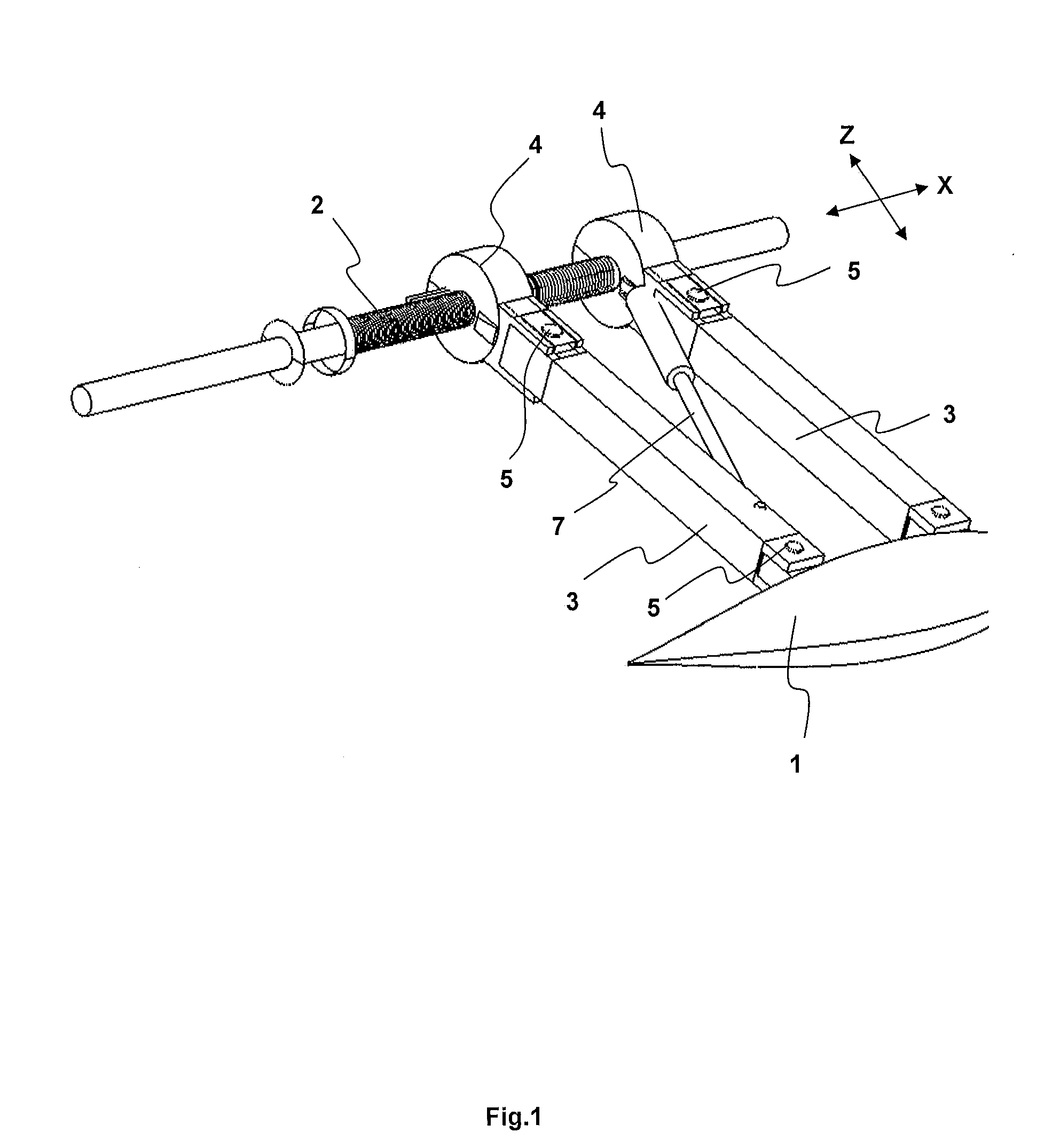
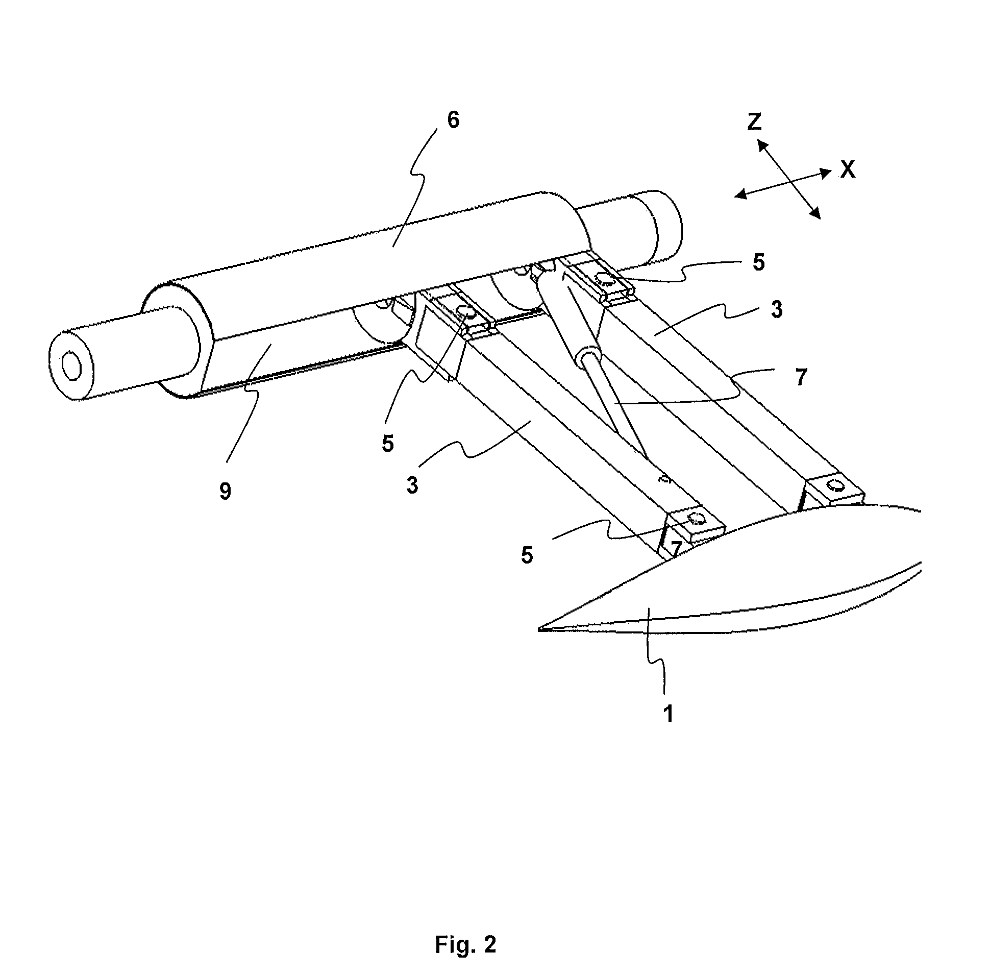
[0031]As illustrated in FIG. 1, the keel (1) is coupled to a threaded shaft (2) by means of arms (3) and of threaded arm-coupling elements (4) connected with these arms (3). Said threaded shaft (2) comprises an endless screw, and the threads formed on the inner surface of the arm coupling elements (4), which (i.e. inner surface) is positioned on the threaded shaft (2), are designed so as to cooperate with the threads of the threaded shaft. As the threaded shaft is rotated the keel (1) moves linearly along the axis (x) extending from the fore end to rear end of the sailboat.

[0032]Pins (5) are provided between the arms (3) and the threaded arm-coupling elements (4) in order to swing the arms (3) around the axis (y) extending from larboard to starboard of the sailboat. Similarly, other pins (5) are provided between the arms (5) and the keel connection for rotating the arms (3) relative to the keel (1). The drive required for swinging the keel (1) around the axis (y) extending from larb...


PUM


Abstract

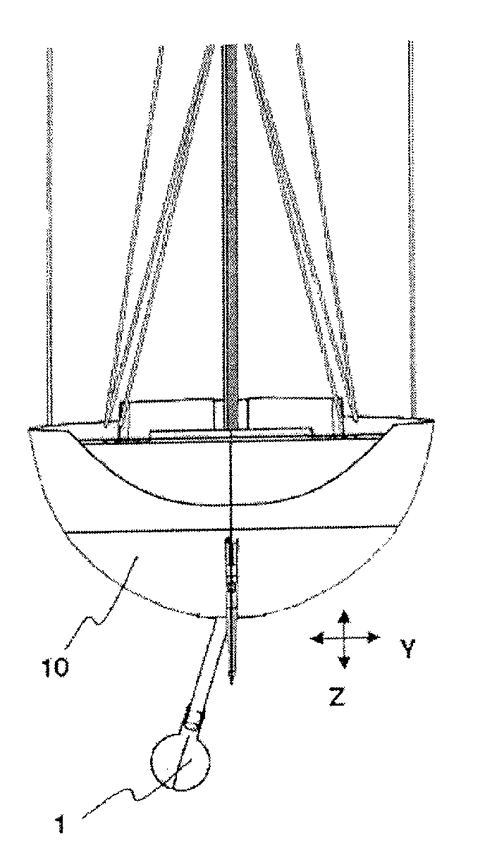
A keel (1) mechanism for a sailboat (10), wherein the keel (1) comprises a drive mechanism for moving the keel (1) linearly along the axis (x) extending from the fore end to rear end of the sailboat (10), and swinging the keel around the axis (x) extending from the fore end to rear end of the sailboat (10), and swinging the keel around the axis extending from larboard to starboard of the sailboat in response to conditions taking place.

Description

FIELD OF INVENTION[0001]The present invention relates to a mechanism for sailboats, which provides the driving or moving of the keel, in three-dimensional space, extending downwards from the boat's underwater hull in response to certain conditions, particularly when forces exerted on the sail in various directions due to wind.BACKGROUND OF INVENTION[0002]Since the energy required for driving sailboats in water is afforded from the wind, the geometrical form and size of the a sail which confronts the wind force become very crucial with respect to the sailing capability of the boat. On the other hand, the stable floating of the sailboat on the water depending on the wind force is directly related to the location of the boat's center of gravity.[0003]The wind exerting throughout the sail's surface area generates force and this force produces a moment so that the boat is forced to tip to various directions as a result of this moment. As a matter of fact, if no balancing effect is provid...

Claims


Application Information

Patent Timeline
Patent Type & Authority Applications(United States)
IPC IPC(8): B63B41/00
CPCB63B41/00
Inventor ULGEN, MEHMET NEVRES
Owner AMGEN FREMONT INC
Learn More