Interior corner mounting module for rope light system

a technology of mounting module and rope light, which is applied in the direction of washstands, scaffold accessories, lighting support devices, etc., can solve the problems of rope light being the amount of rope light that can bend, the practical length of rope light, and the new limiting factor of power utilization of leds

Inactive Publication Date: 2010-05-27
INNOVATIVE LIGHTING LLC
View PDF101 Cites 10 Cited by
  • Summary
  • Abstract
  • Description
  • Claims
  • Application Information

AI Technical Summary

Benefits of technology

[0006]To meet these needs, the present invention generally provides a mounting module for a continuous rope light that is compatible with other mounting modules configured in a structural rope light system. The rope light mounting module is designed to attach to a structure in an interior corner without interrupting the rope light by a break in the extrusion or integrated electrical conductors. The module would hold the rope light at a flexure curve that assures an amount of stress non-detrimental to the internal conductors, light emitting diodes or other integrated components of the rope light.
[0008]In another aspect of the invention, the rope light mounting module would include connection elements such as a set of mated extensions and cavities to connect the ends of the interior corner module to other modules of the rope light mounting system. The connection elements would connect to each other in a seemingly seamless manner to enhance the aesthetic flow of the system.
[0009]In another aspect of the invention, a rope light mounting module is manufactured as a two piece construct with each of the two pieces being identical to each other. Such a design configuration would allow ease of manufacturing, assembly and parts maintenance.
[0010]A significant benefit provided by the present invention is that the interior corner mount would allow the mounting of a continuous rope light across an interior corner without the need of interruption to the rope light itself. Other advantages include an uninterrupted aesthetic to the rope light mounting system, ease of installation and efficiency of manufacture.

Problems solved by technology

This extruded configuration increased the practical length of the rope light greatly as the power utilization of the LEDs became the new limiting factor.
A new limiting factor introduced with the extruded rope light is the amount the rope light can bend before stressing or breaking the internal components in the extrusion.

Method used


Image

  • Interior corner mounting module for rope light system
  • Interior corner mounting module for rope light system
  • Interior corner mounting module for rope light system

Examples


Embodiment Construction

[0020]In the following detailed description, reference is made to the accompanying drawings which form a part hereof, and in which is shown by way of illustration specific embodiments in which the invention may be practiced. These embodiments are described in detail sufficient to enable those skilled in the art to practice the invention, and it is to be understood that other embodiments may be utilized and that structural, logical and mechanical changes may be made without departing from the spirit and scope of the present invention. The following detailed description is, therefore, not to be taken in a limiting sense, and the scope of the present invention is defined by the appended claims.

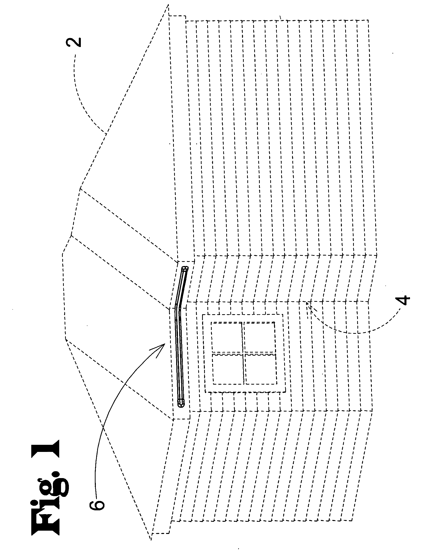
[0021]FIG. 1 depicts a structure (2) or building such as a house that includes and interior corner (4) or a pair of surfaces adjoined at an acute or obtuse angle. On the edge of the roof is depicted a rope light system (6) that is mounted along an interior corner (4) section of the roof's perimet...


PUM


Abstract

A mounting module for a rope light system which easily attaches to the surfaces of an interior corner of a structure that can retain and support a rope light without the need of a junction or brake in the rope light by holding the rope light in a flexure curve that does not stress the LEDS or electrical conductors of the rope light.

Description

FIELD OF THE INVENTION[0001]The present invention relates to a mounting device for a continuous rope light intended to extend over an interior corner of a structure. The mount would be part of a system for mounting a continuous or a contiguous series of rope lights onto a plurality of topological surfaces such as a building exterior.BACKGROUND[0002]The external ornamentation of a structure such as a house or a building is well known in the industry especially for the purposes of holiday lighting and / or advertising indicia. Initially strings of incandescent lights were used that required no more than simple hooks to mount them to a structure. The next evolution of exterior structure lighting employed series of light emitting diodes (LEDs) and their supporting electrical conductors enveloped within a flexible, translucent plastic tube which were to become known as a rope lights. These early rope lights were produced in lengths limited to the manufacturing limitations of the external t...

Claims


Application Information

Patent Timeline
Patent Type & Authority Applications(United States)
IPC IPC(8): A47B96/06
CPCF21S4/007F21S8/037F21Y2101/02F21V15/015F21W2121/004F21V15/01F21S4/26F21Y2115/10
Inventor BAUER, JOSHUA G.
Owner INNOVATIVE LIGHTING LLC
Why Eureka
Try Eureka