Side airbag apparatus for a vehicle

a technology for side airbags and vehicles, which is applied in the direction of vehicle components, pedestrian/occupant safety arrangements, vehicular safety arrangments, etc., can solve the problems of a longer time for the deployed side airbag to reach, and the need for airbags to be deployed for a longer period of tim

Active Publication Date: 2010-06-10
AUTOLIV DEV AB
View PDF13 Cites 4 Cited by
  • Summary
  • Abstract
  • Description
  • Claims
  • Application Information

AI Technical Summary

Problems solved by technology

Because this installation requires that there is a long distance between the airbag attachment point and the seat cushion part to be restrained by the airbag, a problem arises in that it takes a relatively long period of time for the deployed side airbag to reach the part of the seat near the occupant's hips.
Structuring a side airbag apparatus in this manner, however, raises another problem that the inflation gas flows in a forward direction (toward the front of the vehicle) along the configuration of the side airbag, rather than in the desired downward direction.
Thus, a greater amount of time is required for the airbag to reach the seat occupant's hip region.

Method used


Image

  • Side airbag apparatus for a vehicle
  • Side airbag apparatus for a vehicle
  • Side airbag apparatus for a vehicle

Examples


Embodiment Construction

[0022]Detailed embodiments of the present invention are disclosed herein. It is understood however, that the disclosed embodiments are merely exemplary of the invention and may be embodied in various and alternative forms. The figures are not necessarily to scale; some figures may be exaggerated or minimized to show details of a particular component. Therefore, specific structural and functional details disclosed herein are not to be interpreted as limiting but merely as a representative basis of the claims and for teaching one skilled in the art to practice the present invention.

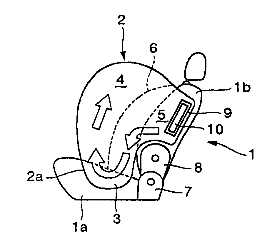
[0023]The side airbag apparatus for a vehicle invention is intended for installation to a vehicle seat of the type having a mechanism, for example, a hinge mechanism which allows the backrest to fold down flat over the seat cushion. In cases where it is required that an airbag provide occupant restraint in the area adjacent to the seat cushion, the side airbag apparatus invention is able to quickly deploy t...


PUM


Abstract

In at least one embodiment, the present invention provides a side airbag apparatus for a vehicle having a seat with a back rest part and a hinge mechanism. The side airbag includes a separation means defining a front airbag chamber and a rear airbag chamber within the side airbag. A connecting passage connects the front and a rear airbag chambers adjacent a lower extremity of the separation means. An attaching portion provided on the rear portion of the rear airbag chamber attaches the side airbag to the backrest part. An inflator proximate said attaching portion injects gas into the rear airbag chamber which flows through the connecting passage into the front airbag chamber.

Description

CROSS REFERENCE TO RELATED APPLICATIONS[0001]This application is a divisional application of and claims priority to U.S. patent application Ser. No. 11 / 667,208 filed May 4, 2007, which claims priority to PCT Patent Application PCT / JP2005 / 19873 filed Oct. 28, 2005, and Japan Patent Application 2004-321317 filed Nov. 4, 2004.FIELD OF THE INVENTION[0002]The present invention relates to a side airbag apparatus for a vehicle.BACKGROUND OF THE INVENTION[0003]Japanese Patent Publication No. 2000-318565 describes an airbag apparatus designed for fast deployment to protect the head of the vehicle occupant. This airbag apparatus incorporates a tube-shaped 1st gas channel formed along the edge of the airbag corresponding to the occupant's head, a 2nd gas channel formed along the boundary area of the airbag corresponding to occupant's head and shoulder and having one end connected to the 1st gas channel, a gas inlet port connected to the 1st gas channel as means of directing gas from the inflat...

Claims


Application Information

Patent Timeline
Patent Type & Authority Applications(United States)
IPC IPC(8): B60R21/20B60R21/231B60R21/2346
CPCB60R21/207B60R2021/23146B60R21/2346B60R21/233
Inventor SHIMONO, HIROYOSHI
Owner AUTOLIV DEV AB
Why Eureka
Try Eureka