Occupant restraint system including side airbag with vent hole

a technology of occupant restraint and side airbag, which is applied in the direction of pedestrian/occupant safety arrangement, vehicular safety arrangment, vehicle components, etc., can solve the problems of airbag excessive deflation, difficulty in gently restrainting the occupant, and increased peak acceleration and rebound phenomenon of the occupant, so as to reduce the pressure of the inflatable part, prevent rebound phenomenon, and reduce the effect of peak acceleration

Inactive Publication Date: 2005-08-23
HONDA MOTOR CO LTD
View PDF9 Cites 31 Cited by
  • Summary
  • Abstract
  • Description
  • Claims
  • Application Information

AI Technical Summary

Benefits of technology

[0009]Furthermore, it is a second object of the present invention to prevent excessive deflation of an airbag and ensure a sufficient period of time for restraining an occupant, while reducing the peak acceleration exerted on the occupant by the airbag being deployed into a curtain shape along an inner side face of an occupant compartment and preventing a rebound phenomenon.
[0021]With this arrangement, if the side collision sensor detects a vehicle side collision, then the control means opens the open / close valve for opening and closing the vent hole. Therefore, when a strong impact is momentarily exerted at the time of the side collision, the gas is released through the vent hole to reduce the internal pressure of the airbag, thereby suppressing the peak acceleration exerted on the occupant. Furthermore, if the rollover sensor detects a vehicle rollover, then the control means closes the open / close valve for opening and closing the vent hole, so that the airbag can be maintained in a deployed state for a comparatively long period of time while the rollover continues, thereby reliably restraining the occupant.

Problems solved by technology

The airbag of the conventional occupant restraint system does not include a vent hole, whereby the airbag inflates to become hard when a gas is supplied from an inflator, thus making it difficult to gently restrain the occupant.
Further, there is a possibility that the occupant might suffer an increased peak acceleration and a rebound phenomenon, that is, a phenomenon in which the occupant rebounds from the airbag.
Although providing a vent hole in the airbag so as to release part of the gas therein is conceivable to prevent an excessively increased internal pressure within the airbag, since the vent hole makes it impossible to retain the gas within the airbag, there is a possibility that the airbag might excessively deflate due to a load restraining the occupant, thus shortening the time available for restraining the occupant with the airbag.
On the other hand, when the vehicle rolls over, it is necessary for the airbag to be maintained in a deployed state for a comparatively long period of time, but if a vent hole is provided in the airbag, there is a possibility that the gas might leak through the vent hole and the airbag deflate too soon, resulting in an inadequate performance of restraining the occupant.
If the vent hole is made small or eliminated in order to prevent the early deflation of the airbag, there is then a possibility that the internal pressure of the airbag might excessively increase when the vehicle is involved in a side collision.

Method used


Image

  • Occupant restraint system including side airbag with vent hole
  • Occupant restraint system including side airbag with vent hole
  • Occupant restraint system including side airbag with vent hole

Examples


first embodiment

[0043]the present invention is explained below by reference to FIGS. 1 to 5.

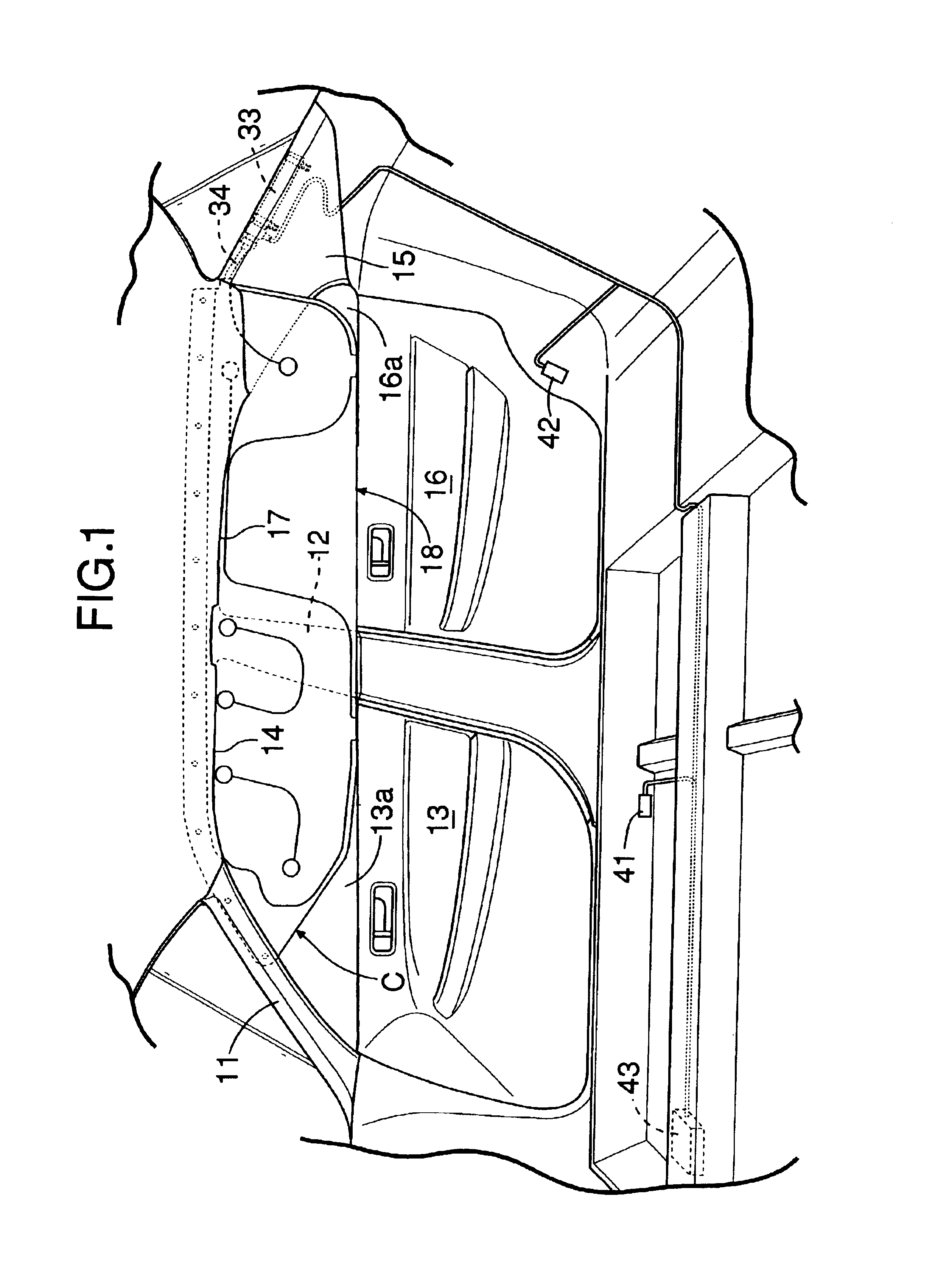
[0044]Referring to FIG. 1, formed between a front pillar 11 and a center pillar 12 on a vehicle body side face is a door opening 14 in which a front door 13 is mounted, and formed between the center pillar 12 and a rear pillar 15 is a door opening 17 in which a rear door 16 is mounted. A roof side rail (not illustrated) extends in the longitudinal direction of the vehicle body so as to provide a connection between the upper end of the front pillar 11 and the upper end of the rear pillar 15, the roof side rail defining the upper edges of the door openings 14 and 17 of the front door 13 and the rear door 16. An occupant restraint system C is provided along the roof side rail. The occupant restraint system C is provided on each of the left and right sides of the vehicle body, the two having substantially identical structures, and that provided on the right side of the vehicle body is representatively described ...

second embodiment

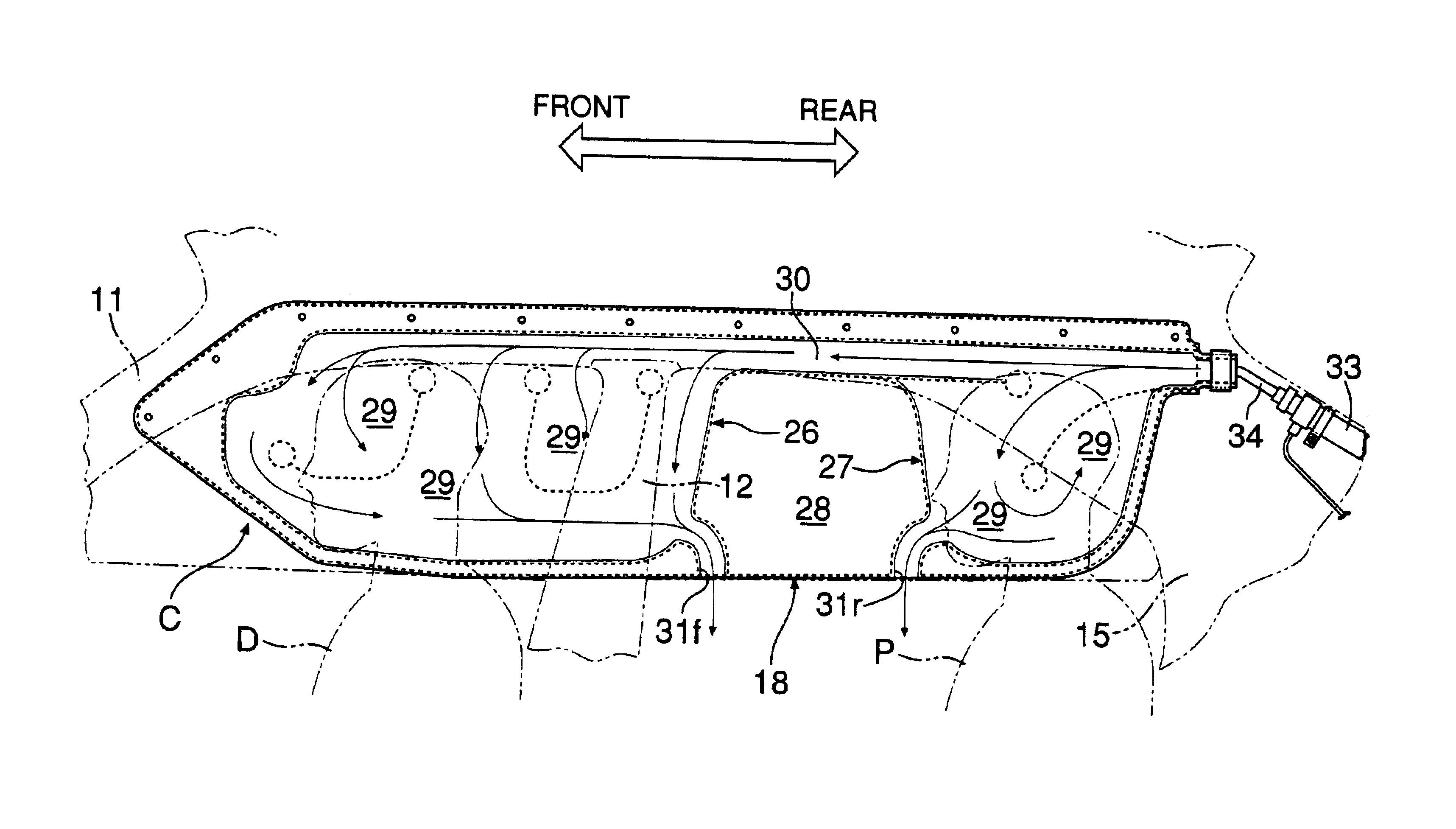
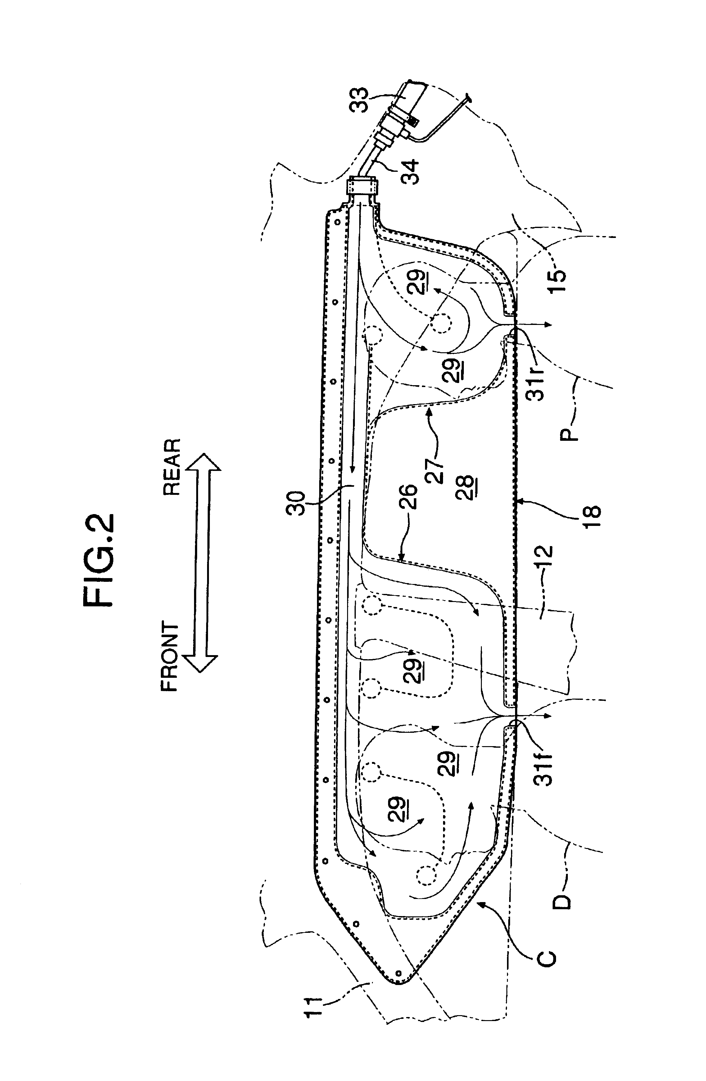
[0054]In the second embodiment, two vent holes 31f are formed in a front protection area 26, whose inflatable parts 29 have a capacity larger than that of the rear protection area 27. This enables excess gas to be more reliably discharged from the inflatable parts 29 of the front protection area 26.

third embodiment

[0055]the present invention is now explained by reference to FIG. 7.

[0056]In the third embodiment, inflatable parts 29 of a front protection area 26 and a rear protection area 27 are formed in vertically extending tubular shapes, and four front vent holes 31f and two rear vent holes 31r are formed at the lower end of the inflatable parts 29 at predetermined intervals. This third embodiment can give the same operational effects as those of the second embodiment.


PUM


Abstract

An occupant restraint system includes an airbag having at least one vent hole and an inflator. The airbag is inflated by a gas generated by the inflator when there is a vehicle collision, and deploys into a curtain shape along an inner side face of an occupant compartment. Since the vent holes, through which gas is discharged from an inflatable part of the airbag, are made to open downward at the lower edge of the airbag, not only is it possible to reliably prevent the inflatable part from being excessively inflated, and thereby from becoming hard resulting in a failure to gently restrain an occupant, but also it is possible to prevent the vent holes from being blocked by the vehicle body or an occupant, thus reliably exhibiting a gas discharge function and preventing the gas discharged though the vent holes from directly impinging on the occupant.

Description

BACKGROUND OF THE INVENTION[0001]1. Field of the Invention[0002]The present invention relates to an occupant restraint system in which an airbag is disposed in a folded state along an upper edge of a door opening of a vehicle body and the airbag is inflated by a gas generated by an inflator when the vehicle is involved in a side collision or a rollover so that it is deployed into a curtain shape along an inner side face of an occupant compartment.[0003]2. Description of the Related Art[0004]A conventional occupant restraint system is known in, for example, Japanese Patent Application Laid-open Nos. 2000-33847 and 11-235965. The airbag of this type of occupant restraint system includes an inflatable part that inflates when a gas is supplied thereto and is deployed along the inner side face of an occupant compartment to restrain an occupant.[0005]The airbag of the conventional occupant restraint system does not include a vent hole, whereby the airbag inflates to become hard when a gas...

Claims


Application Information

Patent Timeline
Patent Type & Authority Patents(United States)
IPC IPC(8): B60R21/16B60R21/00B60R21/213B60R21/232B60R21/233B60R21/235B60R21/239B60R21/276
CPCB60R21/232B60R21/276B60R21/239B60R2021/0006B60R2021/0018B60R2021/23316B60R2021/23595B60R2021/2765
Inventor IKEDA, KOJIYASUHARA, FUMITOSHIOCHIAI, FUMIHARU
Owner HONDA MOTOR CO LTD
Why Eureka
Try Eureka