Plasma display panel and method of driving the same

a technology of display panel and display panel, which is applied in the direction of static indicating device, address electrode, instrument, etc., can solve the problems of reduced display luminance, difficult control of light-emission luminance, and longer scanning period (a) , so as to reduce the ratio of data-writing discharge generation, shorten the scanning period, and improve the effect of accuracy

Inactive Publication Date: 2005-06-16
PANASONIC CORP
View PDF11 Cites 12 Cited by
  • Summary
  • Abstract
  • Description
  • Claims
  • Application Information

AI Technical Summary

Benefits of technology

[0057] In view of the above-mentioned problems in the conventional plasma display panels, it is an object of the present invention to provide a plasma display panel and a method of driving th

Problems solved by technology

This is because it is difficult to control a luminance of light-emission by modulating a voltage, and hence, it is necessary to vary a number of light-emission for controlling a luminance in a conventional AC type plasma display panel.
In the above-mentioned conventional method of driving a plasma display panel, if a number of display lines is increased by accomplishing high accuracy, it is unavoidable that the scanning period (B) is rendered longer, and accordingly, the sustaining period (C) is rendered shorter.
The redu

Method used


Image

  • Plasma display panel and method of driving the same
  • Plasma display panel and method of driving the same
  • Plasma display panel and method of driving the same

Examples


first embodiment

[0106]FIG. 4 is a plan view of a plasma display panel in accordance with the first embodiment of the present invention.

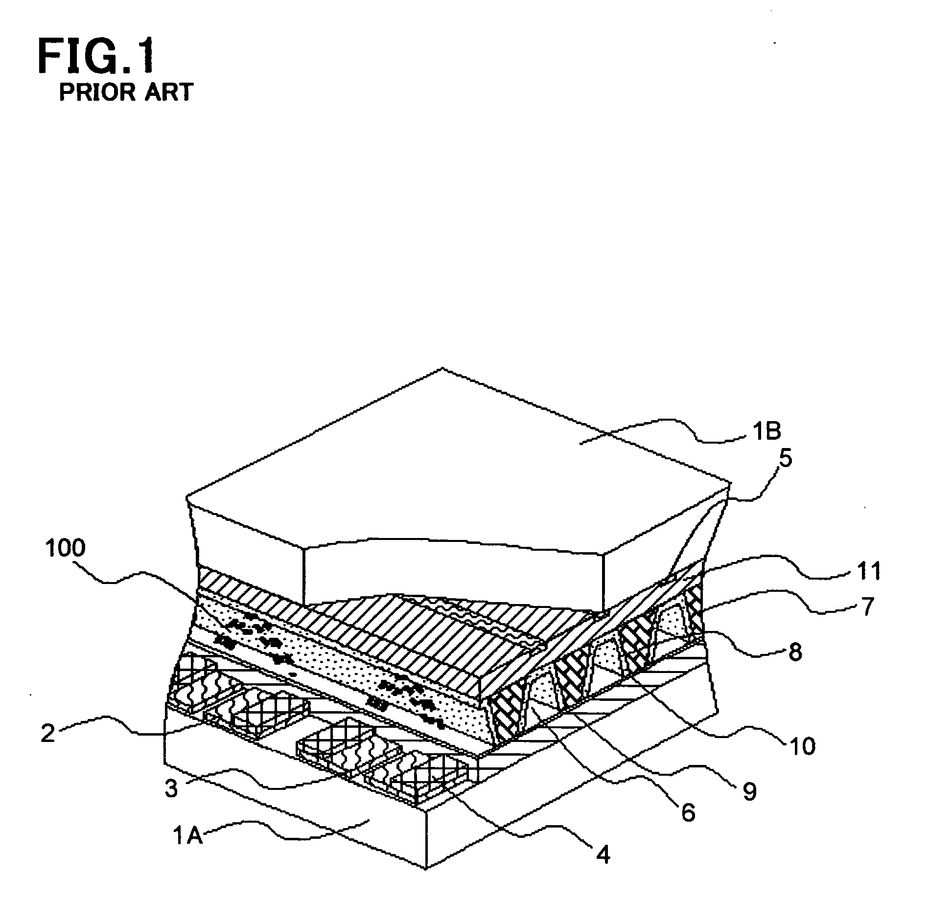
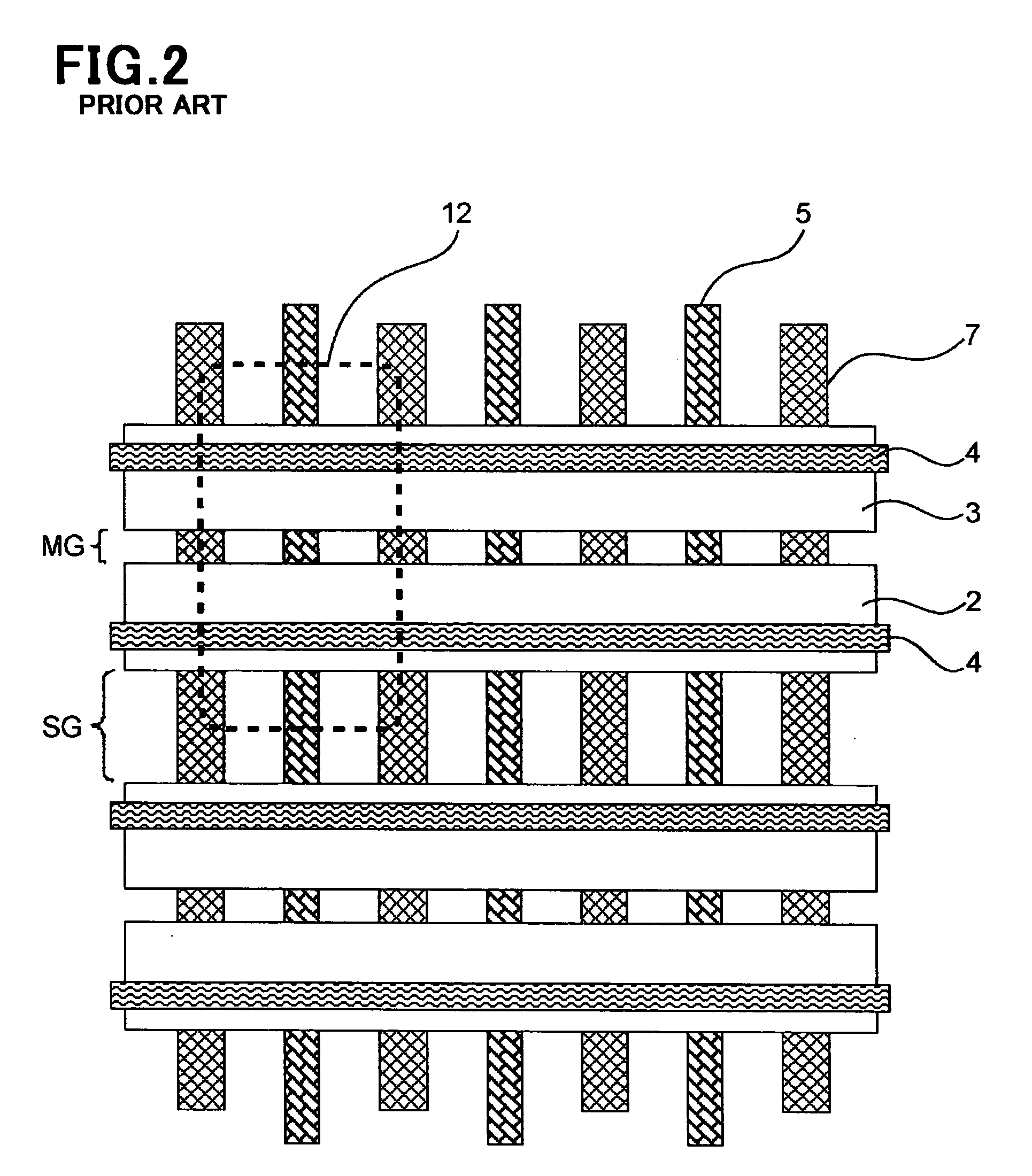
[0107] A plasma display panel in accordance with the first embodiment is structurally different from the conventional plasma display panel illustrated in FIG. 2 only in electrode-arrangement on the front substrate 1A. A plasma display panel in accordance with the first embodiment is structurally identical with the conventional plasma display panel illustrated in FIG. 2 with respect to the rear substrate 1B.

[0108] On the front substrate 1A are formed the transparent scanning electrodes 2 and the transparent sustaining electrodes 3 with the primary discharge gap MG being sandwiched therebetween. The metal trace electrodes 4a and 4b are formed on the scanning and sustaining electrodes 2 and 3, respectively, to reduce a resistance of the electrodes 2 and 3.

[0109] In parallel with the sustaining electrode 3 extends a priming electrode 13 at an opposite side about the ...

second embodiment

[0174]FIG. 8 is a plan view of a plasma display panel in accordance with the second embodiment of the present invention.

[0175] The plasma display panel in accordance with the second embodiment is structurally identical with the plasma display panel in accordance with the first embodiment except that the preliminary scanning electrode 14 is designed not to extend beyond the display cell 12. Specifically, the preliminary scanning electrode 14 in the second embodiment is formed individually below each of the partition wall 7. Unlike the preliminary scanning electrode 14 in the first embodiment, the preliminary scanning electrode 14 in the second embodiment is not continuous with adjacent preliminary scanning electrodes 14.

[0176] Hereinbelow is explained a method of driving the plasma display panel in accordance with the second embodiment.

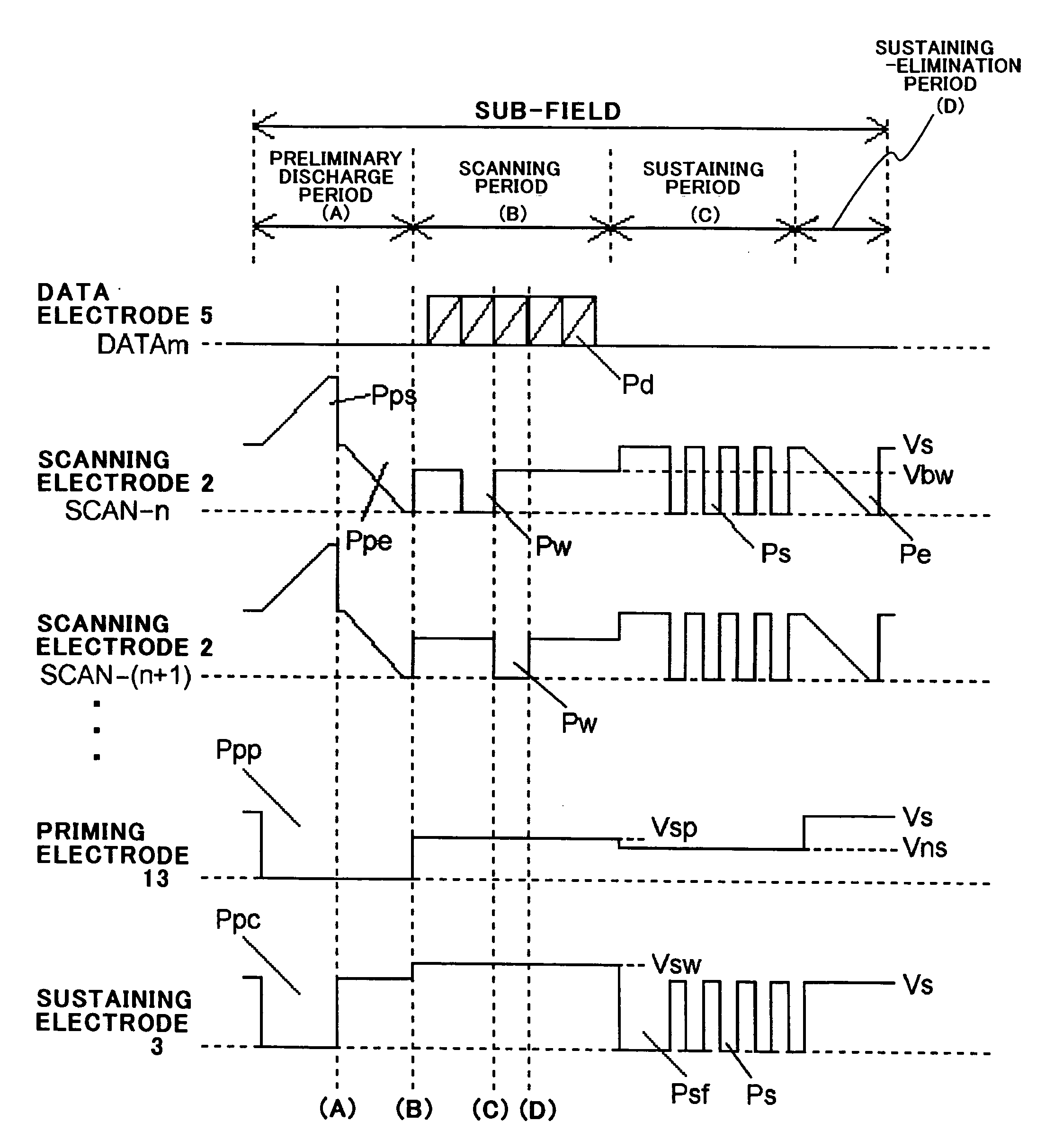
[0177]FIG. 9 is a timing chart showing waveforms of voltage pulses to be applied to electrodes in the method. FIG. 9 shows successive two sub-field...

third embodiment

[0187]FIG. 10 is a plan view of a plasma display panel in accordance with the third embodiment of the present invention.

[0188] The plasma display panel in accordance with the third embodiment is structurally identical with the plasma display panels in accordance with the first and second embodiments except that the partition walls 7 are designed to extend further in a horizontal direction between display lines, that is, in parallel with the scanning and sustaining electrodes 2 and 3. That is, the partition walls 7 in the third embodiment are in the form of a grid.

[0189] The preliminary scanning electrode 14 is electrically connected to the scanning electrode 2 in an adjacent display cell 12 through the cross-link 4c extending across the horizontally extending partition walls 7.

[0190] The plasma display panel in accordance with the third embodiment is driven in accordance with the method having been explained in the first and second embodiments. Similarly to the first and second e...


PUM


Abstract

A plasma display panel includes (a) first and second substrates facing each other, (b) a plurality of first electrodes formed on the first substrate and extending in parallel with one another, (c) a plurality of second electrodes formed on the second substrate and extending in parallel with one another perpendicularly to the first electrodes, and (d) a plurality of display cells arranged at intersections of the first electrodes with the second electrodes, wherein a first selection pulse is input into the first electrodes and a second selection pulse is input selectively into one or more of the second electrodes to thereby control whether light is to be emitted in each of the display cells, and at least one of the display cells has a third electrode formed on the first substrate and being electrically connected to a first electrode other than a first electrode belonging to a display cell to which the third electrode belongs.

Description

BACKGROUND OF THE INVENTION [0001] 1. Field of the Invention [0002] The invention relates to a plasma display panel, and more particularly to a plasma display panel and a method of driving the same both of which are capable of stably displaying images even when much images are to be displayed. [0003] 2. Description of the Related Art [0004] A conventional plasma display panel, a conventional method of driving the same and a conventional method of controlling a luminance in a plasma display panel are explained hereinbelow with reference to FIGS. 1 to 3. [0005]FIG. 1 is a perspective broken view of a conventional plasma display panel suggested in Japanese Patent Application Publications Nos. 2000-11899 and 2001-76625, for instance. [0006] A plasma display panel includes an electrically insulating front substrate 1A and an electrically insulating rear substrate 1B both of which are composed of glass. [0007] On the electrically insulating front substrate 1A are formed transparent scanni...

Claims


Application Information

Patent Timeline
IPC IPC(8): G09G3/20G09G3/288G09G3/291G09G3/292G09G3/293G09G3/294G09G3/298H01J11/12H01J11/22H01J11/24H01J11/26H01J11/28H01J11/34H01J11/36H01J11/44
CPCG09G3/2986H01J11/28H01J11/12G09G3/291H01J11/20
Inventor TANAKA, YOSHITOFURUTANI, TAKASHI
Owner PANASONIC CORP
Why Eureka
Try Eureka