Radio resource control-service data unit reception

a technology of radio resource control and data unit, applied in the direction of instruments, coding, code conversion, etc., can solve the problems of utilization, reducing the performance of system functions requiring system information and or increasing reception, and reducing radio resource efficiency

Active Publication Date: 2005-03-29
INTERDIGITAL TECH CORP
View PDF4 Cites 93 Cited by
  • Summary
  • Abstract
  • Description
  • Claims
  • Application Information

AI Technical Summary

Problems solved by technology

However, when an RRC-SDU is transported in the transparent or unacknowledged modes, the RLC and MAC layers of the receiving side are not aware of the RRC-SDU.
Additionally, to maintain proper performance of these system functions, SIB repetition rates may have to be increased to compensate for failed transmissions, which reduces radio resource efficiency and utilization.
The first area i

Method used


Image

  • Radio resource control-service data unit reception
  • Radio resource control-service data unit reception
  • Radio resource control-service data unit reception

Examples


Embodiment Construction

)

The preferred embodiment of the present invention will be described with reference to the drawing figures wherein like numerals represent like elements throughout.

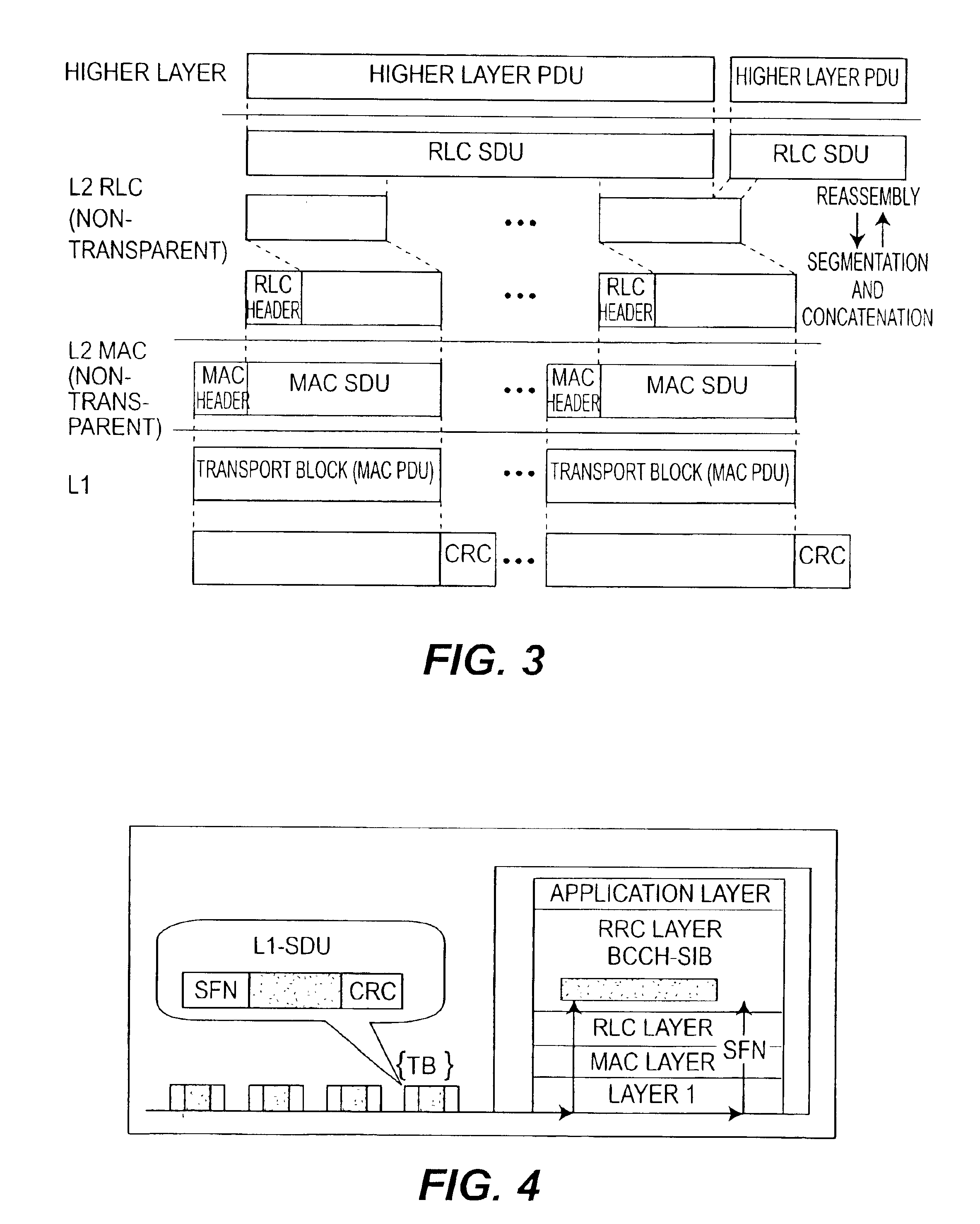
Referring back to FIG. 4, the UE-L1 passes a received TB set, the SFN, and the CRC-error-detection result of each TB to the higher layers, (L2 and L3). Since the MAC and RLC layers 24, 25 operate in transparent mode for the BCCH, for example, the BCCH TBs can be forwarded to the L3 without processing. It is also possible that TBs with CRC errors are discarded by L2 or L3 before forwarding to L3.

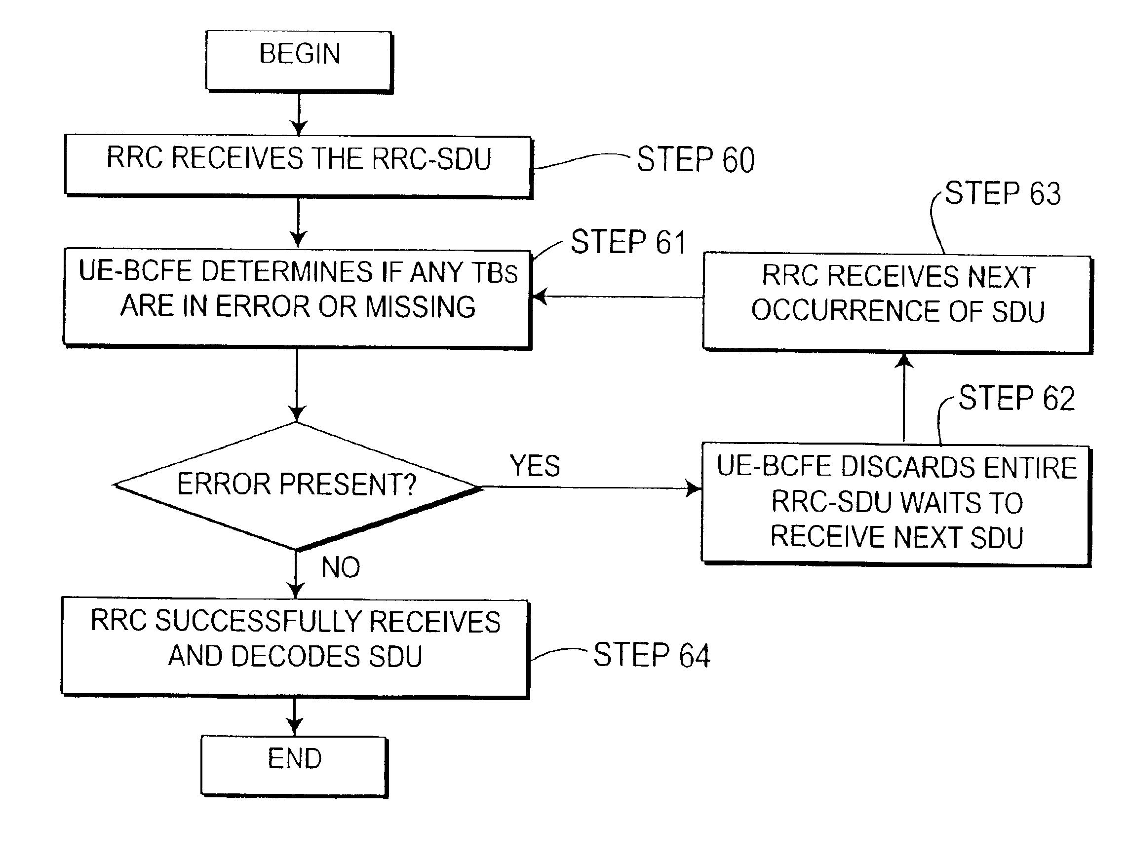
FIGS. 7 and 8 are an illustration and flow diagram, respectively, of the method used in the preferred embodiment of the present invention. FIG. 7 illustrates an example scenario wherein an RRC-SDU is composed of nine (9) TBs with a repetition period of 64 frames. The UE-BCFE is informed in advance to expect the RRC-SDU from SFN=2 to SFN=to 18. The UE-BCFE receives the set of TBs corresponding to the RRC-SDU from one of the Node Bs ...


PUM


Abstract

A method for processing a received communication which includes periodic transmissions of a set of information segments. A first transmission of the set of information segments is received and processed to identify each of the segments as valid or invalid. The valid segments of the first set are then stored. Where all segments of the set are not stored, subsequent transmissions of the set of information segments are received and only those segments not previously stored are processed to identify each such segment as valid or invalid. The valid segments so identified are then stored. Subsequent transmissions are repeatedly received unless all segments of the set have been stored.

Description

BACKGROUNDThe Universal Mobile Telecommunications Systems (UMTS) network architecture, illustrated in FIG. 1, includes a core network (CN) 2, a UMTS Terrestrial Radio Access Network (UTRAN) 3, and at least one User Equipment (UE) 18, (only one UE 18 being shown for simplicity). The two general interfaces are the Iu interface between the UTRAN and the core network as well as the radio interface Uu between the UTRAN and the UE.The UTRAN consists of several Radio Network Subsystems (RNSs) 10, 11. They can be interconnected by the lur interface. Each RNS 10, 11 is divided into a Radio Network Controller (RNC) 12, 13 and several base stations (Node Bs) 14-17. The Node Bs 14-17 are connected to the RNCs 12, 13 by the lub interface. One Node B 14-17 can serve one or multiple cells.The UTRAN 3 supports both FDD mode and TDD mode on the radio interface. For both modes, the same network architecture and the same protocols are used.Communication between the Node Bs 14-17 and the UEs 18 over th...

Claims


Application Information

Patent Timeline
IPC IPC(8): H04L1/16H04L1/18H04Q7/22H04B7/005H04W28/00H04B7/26H04L29/08H04W28/04H04W80/00
CPCH04L1/1835H04L1/1809H04B7/005
Inventor CHAO, YI-JUTERRY, STEPHEN E.DINEIRO, JULIOMILLER, JAMESWANG, CARLSTERN-BERKOWITZ, JANET
Owner INTERDIGITAL TECH CORP
Why Eureka
Try Eureka