
Computer system and migration method of virtual machine

a virtual machine and computer system technology, applied in computing, instruments, electric digital data processing, etc., can solve problems such as obstructing communication by virtual machines, and achieve the effect of reducing packet loss in the live migration of virtual machines

Active Publication Date: 2012-07-19
NEC CORP
View PDF3 Cites 95 Cited by
  • Summary
  • Abstract
  • Description
  • Claims
  • Application Information

AI Technical Summary

Benefits of technology

[0016]As mentioned above, according to the present invention, the communication with the migration object virtual machine can be switched to the migration destination virtual machine by setting a flow according to the MAC address of the received first packet to the switch. The transfer of the memory image of the virtual machine and the communication with the migration destination virtual machine can be switched by setting the migration destination of the virtual machine to the VM management apparatus at least. Also, in the present invention, because the switching of the destination of the switch is carried out by the flow which is set by the open flow controller, the period of the stop of the virtual machine can be reduced when viewing from the side of the network in accompaniment with the migration of the virtual machine.
[0018]Also, the packet loss in the live migration of the virtual machine can be reduced.

Problems solved by technology

Therefore, there is a fear that the traffic which occurs with the migration of the virtual machine obstructs communication with a migration object virtual machine and another virtual machine.

Method used


Image

  • Computer system and migration method of virtual machine
  • Computer system and migration method of virtual machine
  • Computer system and migration method of virtual machine

Examples


first exemplary embodiment

(Configuration of Computer System)

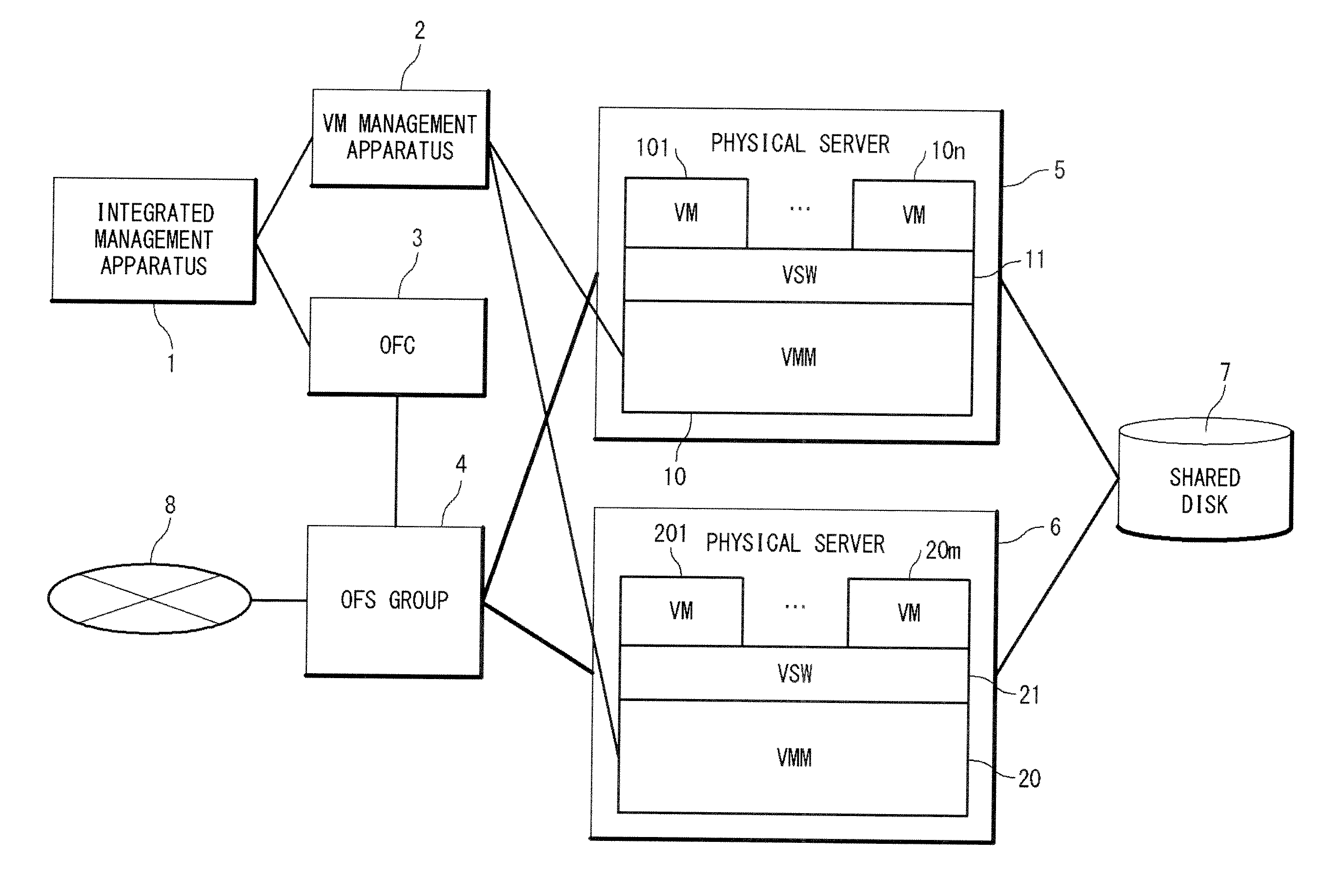
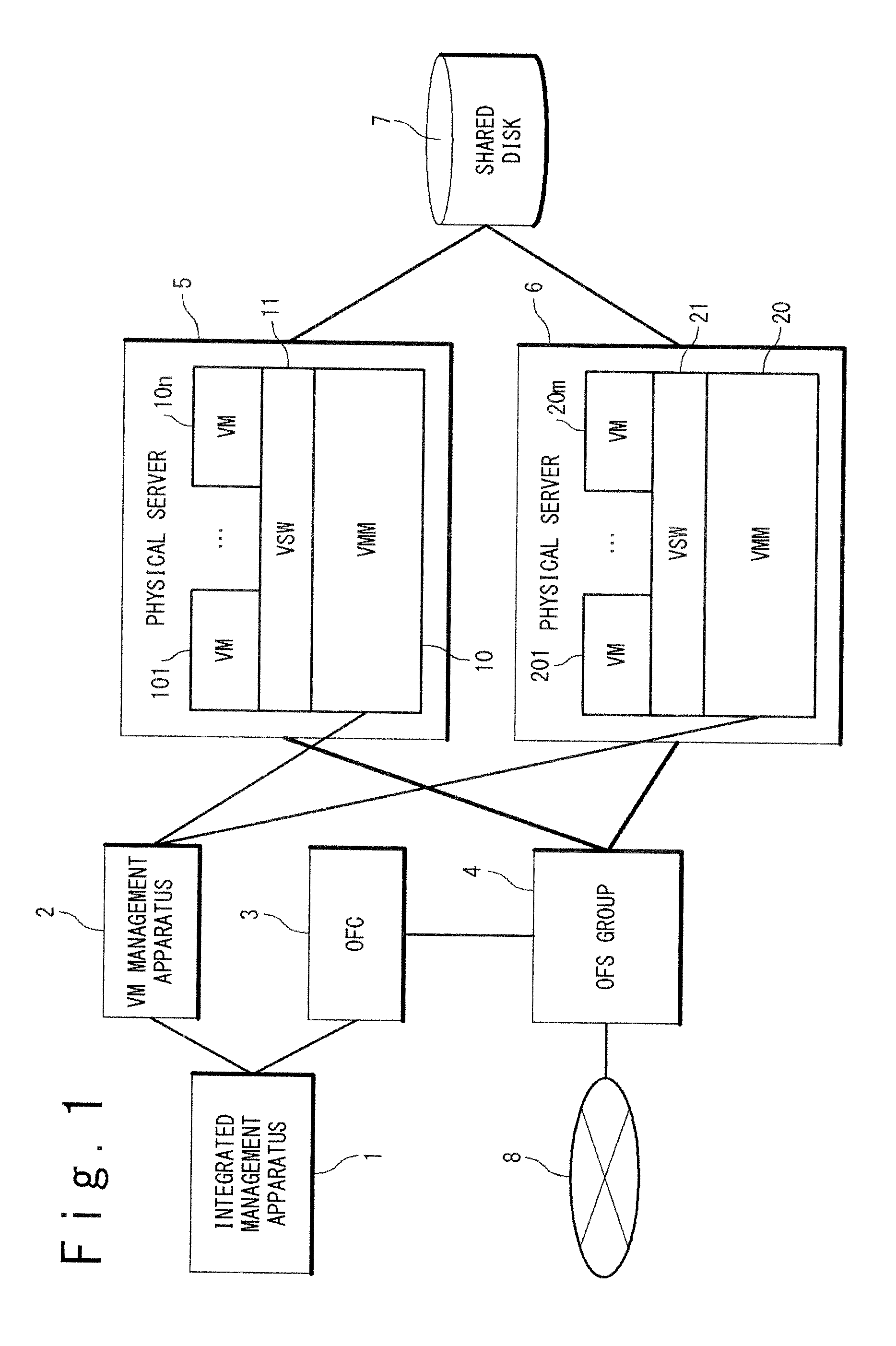
[0038]A configuration of a computer system according to a first exemplary embodiment of the present invention will be described with reference to FIG. 1 to FIG. 9. FIG. 1 is a block diagram showing the configuration of the computer system according to first and second exemplary embodiments of the present invention. The computer system of the present invention is provided with an integrated management apparatus 1, a virtual machine management apparatus 2 (hereinafter, to be referred to as a VM management apparatus 2), an open flow controller 3 (hereinafter, to be referred to as an OFC 3), a switch group 4 (hereinafter, to be referred to as an open flow switch (OFS) group 4), physical servers 5 and 6, a storage unit 7 such as a shared disk.

[0039]The physical servers 5 and 6 are mutually connected through the OFS group 4 which has at least one open flow switch. Also, the physical servers 5 and 6 are connected with an external network 8 such as the Inte...

second exemplary embodiment

[0099]Next, referring to FIG. 11, FIG. 13 and FIG. 14, the migration method of a virtual machine in the computer system according to the second exemplary embodiment of the present invention will be described. Because the configuration of the computer in the second exemplary embodiment is same as the first exemplary embodiment, the description is omitted. The operation which is different from that of the first exemplary embodiment will be described. Also, the same operation as that of the first exemplary embodiment will be described by adding the same numerals.

[0100]In the migration method of the virtual machine in the second exemplary embodiment, the communication flow for the migration destination VM is set to the OFS 4i at the stage of the migration preparation processing. Thus, the packet data for the migration object VM is duplicated and is transferred to both of the migration source VM and the migration destination VM. In the first exemplary embodiment, because the communicatio...

third exemplary embodiment

[0113]Next, referring to FIG. 15 and FIG. 16, the migration method of the virtual machine in the computer system according to a third exemplary embodiment of the present invention will be described. FIG. 15 is a diagram showing a configuration of the computer system according to the third exemplary embodiment of the present invention. Referring to FIG. 15, the computer system in the third exemplary embodiment has a configuration in which the integrated management apparatus 1 is excluded from the computer system in the first exemplary embodiment. Below, the operation which is different from the first exemplary embodiment will be described. Also, the same operation as in the first exemplary embodiment will be described by assigning the same reference numerals.

[0114]In the migration method of the virtual machine in the third exemplary embodiment, the setting for the VM migration is carried out only to the VM management apparatus 2, and the OFC 3 detects a migration destination of the v...


PUM


Abstract

A computer system of the present invention is provided with an open flow controller 3, and a switch 4i. The switch 4i notifies a MAC address contained in packet data to the open flow controller 3 when the packet data from the virtual machine that the migration has completed does not fit with a rule shown by the flow set to the switch itself. The open flow controller 3 sets a communication flow for a migration destination VM generated according to the notified MAC address to the switch 4i. The switch 4i transfers the packet data for said virtual machine which follows a rule 444 shown by the communication flow for said migration destination VM, to the migration destination virtual machine based on an action 445 shown by the communication flow for said migration destination VM.

Description

TECHNICAL FIELD[0001]The present invention is related to a computer system and a migration method of a virtual machine, and more particularly, to a computer system in which a migration of a virtual machine is possible while carrying out integrated management of a network environment and an IT environment.BACKGROUND ART[0002]In recent years, a more flexible system configuration became possible by a plurality of virtual machines operating on one physical server. In such a system, a system load distribution, a failure avoidance and so on can be realized by a migration technique in which an operating virtual machine is migrated to another physical server and a memory area without stopping the operating virtual machine.[0003]As a technique of the migration, for example, WO 2005 / 083569 (Patent Literature 1), JP 2009-146106A (Patent Literature 2), JP 2004-78465A (Patent Literature 3) are known.[0004]Patent Literature 1 discloses a network system which is provided with a switching controlle...

Claims


Application Information

Patent Timeline
IPC IPC(8): G06F9/455G06F15/16H04L45/42
CPCG06F9/4856G06F2009/4557G06F9/45558
Inventor ASHIHARA, KOJIYAMATO, JUNICHI
Owner NEC CORP
Learn More