Frictional spot joining method and frictional spot joining apparatus

a friction spot and joining method technology, applied in the field of frictional jointing, can solve the problems of reduced galvanic corrosion or joining strength, reduced thickness of aluminum existing between the tip of the rotational tool and the lower steel plate, and torn aluminum plate off, etc., to ensure the joining strength, reduce the effect of agitation and sufficient time of agitation

Inactive Publication Date: 2009-04-28
MAZDA MOTOR CORP
View PDF9 Cites 0 Cited by
  • Summary
  • Abstract
  • Description
  • Claims
  • Application Information

AI Technical Summary

Benefits of technology

[0007]The present invention has been devised in view of the above-described problems of the joining of different kinds of metal members that lap over. An object of the present invention is to generate the proper plastic flow of the metal member and thereby to ensure the joining strength with a sufficient period of time of agitation, by maintaining a high temperature enough to soften the metal member and by preventing the rotational tool from coming into the metal member too deeply or from penetrating the metal member.
[0009]Thereby, the first metal member starts to be softened by the frictional heat in the first step, and in the second step, the temperature of the joining portion is promptly increased to the high temperature enough to soften the first metal member by the frictional heat and the plastic flow of the first metal member starts. Then, in the third step, since the pressing force is maintained at the low pressing force, the rotational tool can be prevented from coming into the metal member too deeply and the rotational tool can be held in the specified location. Accordingly, the high temperature enough to soften the first metal member can be maintained and thereby the proper plastic flow of the first metal member can be ensured, preventing the torn-off situation of the first metal member or the penetration of the rotational tool through the metal member. Thus, the proper plastic flow of the metal member can be maintained for a sufficiently long period of time in the third step, thereby ensuring the joining strength.
[0011]According to another embodiment of the present invention, the rotational tool is rotated at a specified rotational speed within a middle rotational speed through a high rotational speed in the first step, at the middle rotational speed in the second step, and at a specified rotational speed within a low rotational speed through the high rotational speed in the third step. Thereby, the first metal member can surely start to be softened by the frictional heat in the first step, the proper agitation of the softened portion of the metal member can be obtained in the second step, and the proper plastic flow can be maintained for a long period of time regardless of the rotational speed in the third step.
[0013]According to another embodiment of the present invention, the rotational tool comprises a ring-shaped concave that is formed at the shoulder portion around the pin portion. Thereby, since the rotational tool with the ring-shaped concave formed at the shoulder portion around the pin portion is used, the first metal member in the plastic flow state is prevented from flowing out from the portion right below the rotational tool and thereby the pressing force of the rotational tool is concentrated upon the portion right below the rotational tool. As a result, the plastic flow of the first metal member can be promoted.
[0015]According to another embodiment of the present invention, the first metal member is made of aluminum alloy, the second metal member is made of steel, and both metal members are joined in a solid state at a joining boundary face thereof. Thereby, since the plastic flow is generated in the first metal member with the lower melting point, the energy necessary to join the first and second metal members can be kept smaller and the joining time can be kept shorter.

Problems solved by technology

Namely, a certain period of time of agitation by the rotational tool under a relatively high pressing force at the terminal stage with both the pin portion and the shoulder portion of the rotational tool pushed into the metal member to generate the proper plastic flow at the metal member would cause an improper situation in which the rotational tool comes into the upper aluminum plate too deeply, so that the thickness of part of the aluminum existing between the tip of the rotational tool and the lower steel plate (remaining thickness) becomes too thin.
Eventually, there would occur a situation in which the aluminum plate has been torn off.
As a result, an aluminum loss would happen at the joining portion, and thus there would occur problems of galvanic corrosion or joining-strength decrease due to a difference in electric potential between the aluminum and the steel at this aluminum-loss portion.
Also, the torn-off aluminum is attached to the rotational tool, which would prevent the rotational tool from properly operating for joining at subsequent joining portions.
As a result, the tip of the pin portion of the rotational tool would be worn improperly.

Method used


Image

  • Frictional spot joining method and frictional spot joining apparatus
  • Frictional spot joining method and frictional spot joining apparatus
  • Frictional spot joining method and frictional spot joining apparatus

Examples


Embodiment Construction

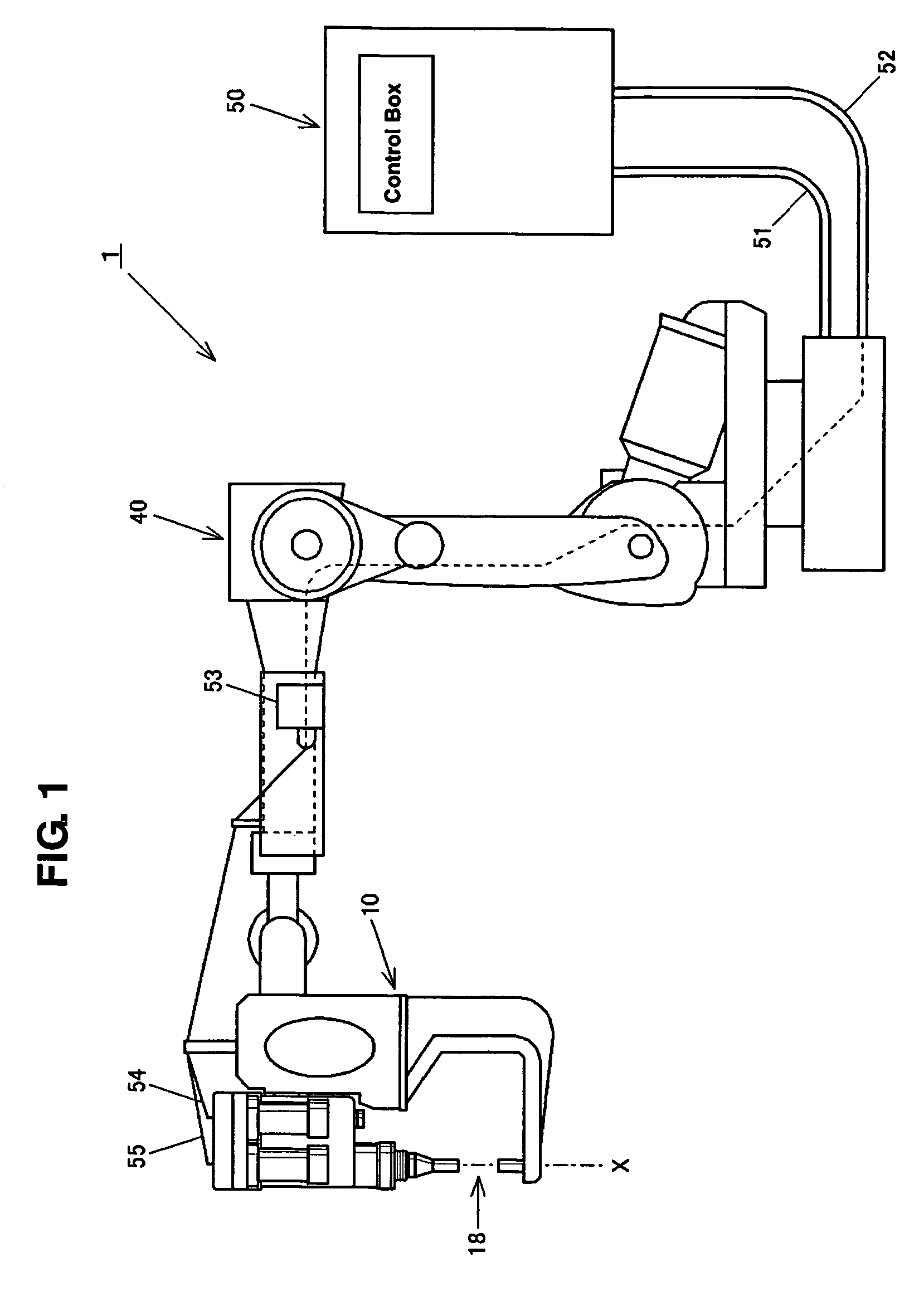
[0049]Hereinafter, a preferred embodiment will be described referring to the accompanying drawings. FIG. 1 is a schematic elevation view of a frictional spot joining apparatus 1 according to the present embodiment. The frictional spot joining apparatus 1 is used for joining of aluminum members or a aluminum member and a steel member of, for example, a body of an automotive vehicle and the like. This apparatus comprises a joining gun 10 and a robot 40 having the joining gun 10 at its hand as a major component. A six-axis multiple-articulated type of robot which has been used widely may be preferably used as the robot 40.

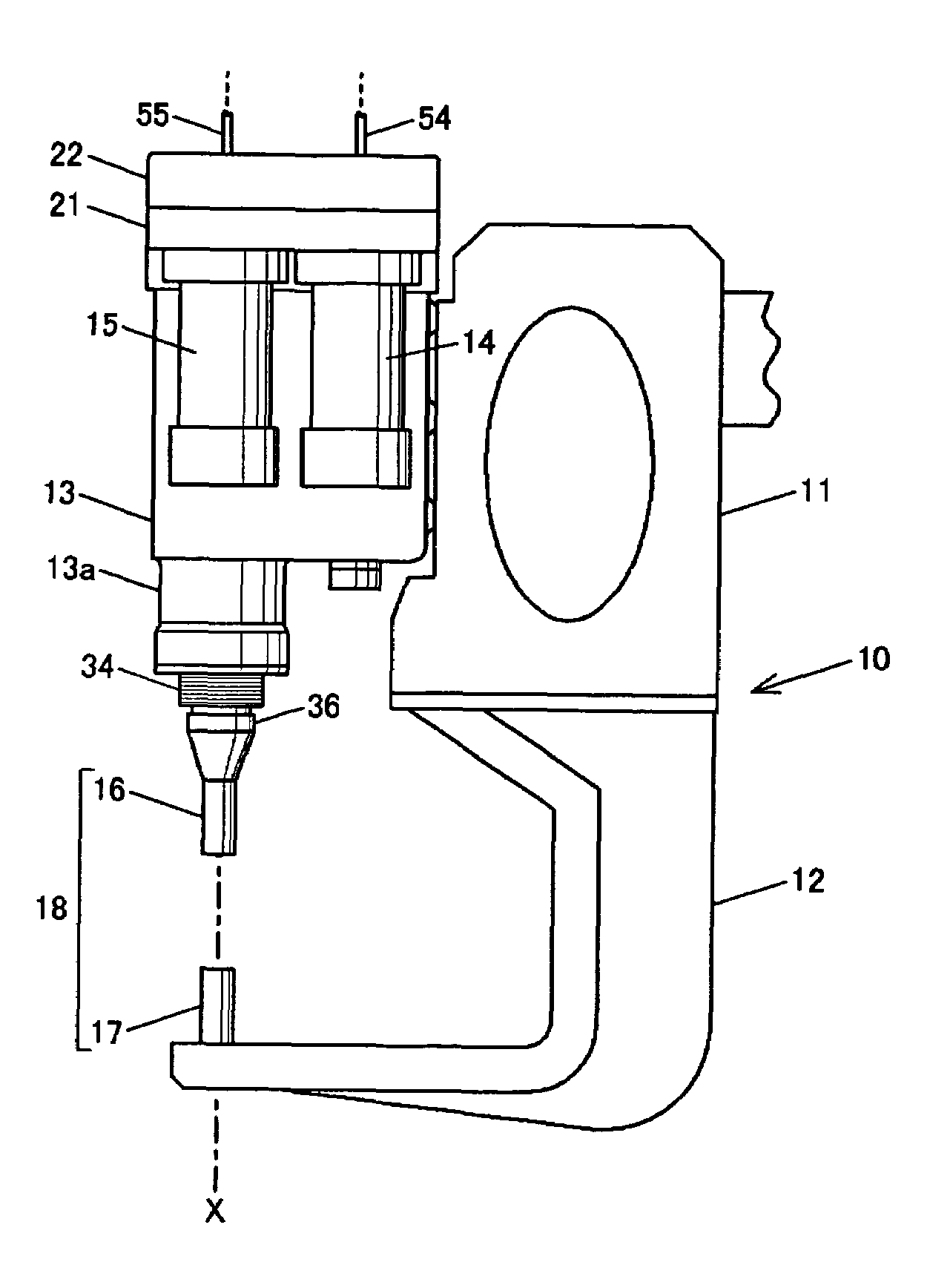
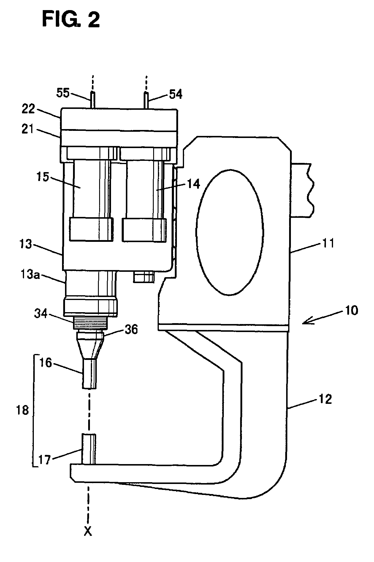
[0050]As illustrated in FIGS. 2 and 3, the joining gun 10 comprises an attaching box 11 attached to the robot 40, a L-shaped arm 12 extending downward from the bottom of the attaching box 11, a body case 13 fixed to the side of the attaching box 11 above the arm 12, a pressing motor 14, and a rotating motor 15. At the lower end of the body case 13 is provided a rotati...


PUM

PropertyMeasurementUnit
pressing forceaaaaaaaaaa

Abstract

In the third step of joining of the metal members, the pressing force of the rotational tool under rotation is maintained at the third pressing force that is smaller than the second pressing force until a specified period of time elapses after the tip of the pin portion of the rotational tool has reached the specified point that is at a distance from the joining face. Accordingly, the proper plastic flow of the metal member can be generated and thereby the joining strength with a sufficient period of time of agitation can be ensured, by maintaining a high temperature enough to soften the metal member and by preventing the rotational tool from coming into the metal member too deeply or from penetrating the metal member.

Description

BACKGROUND OF THE INVENTION[0001]The present invention relates to a frictional jointing, and in particular to a frictional joining technology in which different kinds of metal members that lap over are joined.[0002]Members made of aluminum or aluminum alloy (hereinafter, referred to as “aluminum” simply) have been recently used as a body panel and the like of many automotive vehicles to reduce a vehicle weight. Accordingly, the joining of different kinds of metal members, such as aluminum and iron, or aluminum and steel, has been increasing. The frictional joining is also known as such a joining method. In this frictional joining, there is provided a work that is comprised of a first metal member, for example, that is made of aluminum alloy and a second metal member, for example, that is made of steel and has a higher melting point than the first metal member, which lap over. Then, a rotational tool is pushed against this work from a side of the first metal member, the first metal m...

Claims


Application Information

Patent Timeline
Patent Type & Authority Patents(United States)
IPC IPC(8): B23K20/12
CPCB23K20/123B23K20/1265B23K20/128B23K20/22B23K20/2275
Inventor GENDOU, TOSHIYUKISUGIMOTO, YUKIHIRONISHIGUCHI, KATSUYATAKASE, KENJISHOJI, YOHEI
Owner MAZDA MOTOR CORP
Why Eureka
Try Eureka