Manufacturing method of rotor

a manufacturing method and rotor technology, applied in the direction of dynamo-electric components, dynamo-electric machines, magnetic circuit shapes/forms/construction, etc., can solve the problems of low temperature cracking, difficult to ensure the joining strength of the welded part, and the likelihood of occurring, so as to achieve the effect of ensuring the joining strength

Active Publication Date: 2020-09-17
AISIN CORP
View PDF0 Cites 0 Cited by
  • Summary
  • Abstract
  • Description
  • Claims
  • Application Information

AI Technical Summary

Benefits of technology

[0010]According to the present disclosure, as described above, joining strength can be ensured even when the plate is welded and fixed to the rotation transmitting member composed of a martensitic material.

Problems solved by technology

Although the structure of martensite is harder than the structure of austenite or the structure of ferrite, martensitic material is disadvantageous in that low-temperature cracking, which is cracking that occurs after welding to another member (plate), is likely to occur.
When low-temperature cracking occurs, it is difficult to ensure joining strength of the welded part.

Method used


Image

  • Manufacturing method of rotor
  • Manufacturing method of rotor
  • Manufacturing method of rotor

Examples


Embodiment Construction

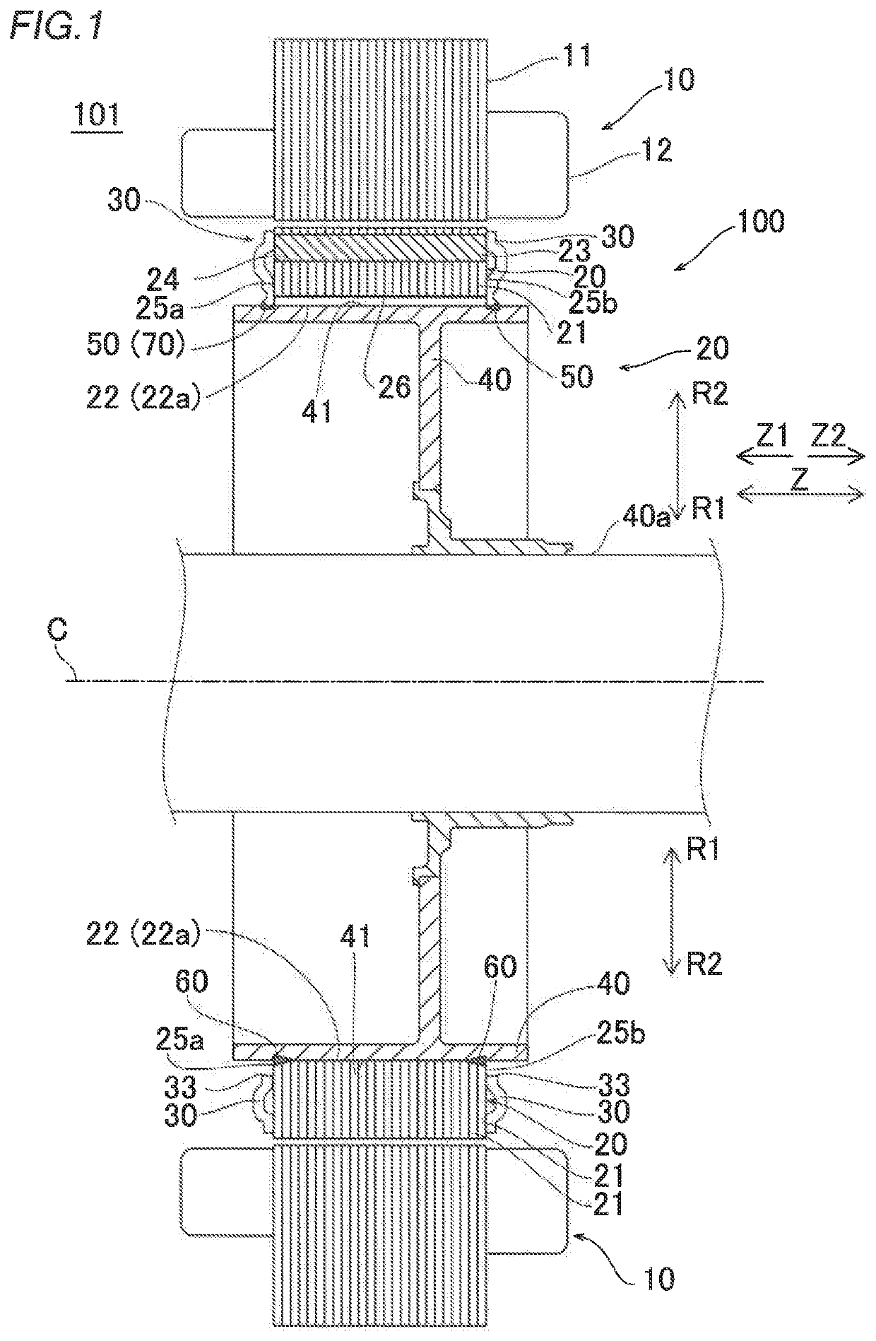
[0028]Hereinafter, an embodiment of the present disclosure will be described with reference to the drawings.

[0029][Rotor Structure]

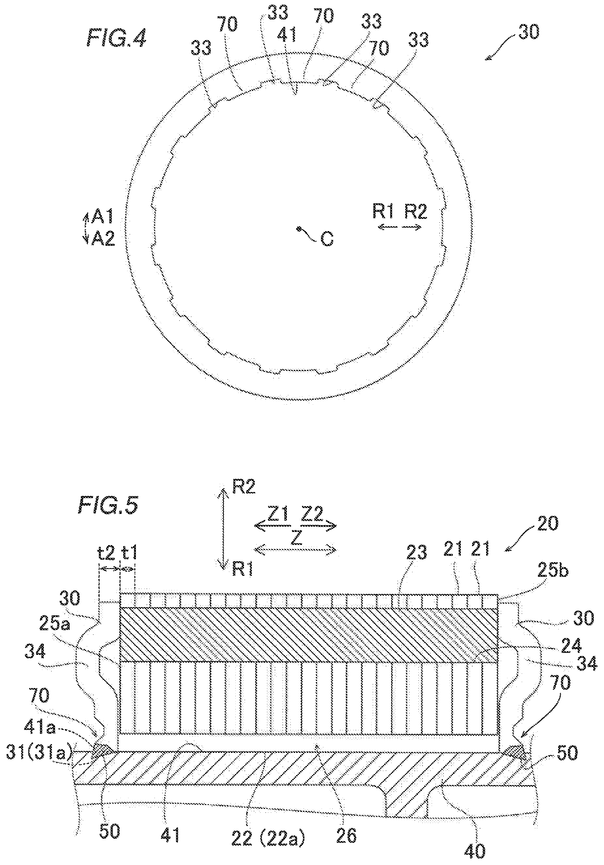
[0030]The structure of a rotor 100 according to the first embodiment will be described with reference to FIGS. 1 to 8.

[0031]In the present specification, a “rotational axis direction” means a direction along a rotational axis C of the rotor 100 (Z direction, see FIG. 1). A “circumferential direction” means a circumferential direction of the rotor 100 (arrow Al direction or arrow A2 direction, see FIG. 2). Further, “radially inward” means a direction toward the center of the rotor 100 (arrow R1 direction). In addition, “radially outward” means a direction toward the outside of the rotor 100 (arrow R2 direction).

[0032]As illustrated in FIG. 1, the rotor 100 forms a part of a rotating electrical machine 101. For example, the rotating electrical machine 101 is configured as an inner rotor type rotating electrical machine. That is, in the rotating electrical ...


PUM

PropertyMeasurementUnit
inclination angle θ1aaaaaaaaaa

Abstract

The manufacturing method of a rotor includes: a step of preparing a plate that is composed of an austenitic material and that has a projected portion and a part with a width in a rotational axis direction smaller than a width of the projected portion in the rotational axis direction; and a step of forming a welded portion across the projected portion of the plate and a rotation transmitting member by emitting an energy beam on at least a part of the projected portion to melt at least a part of the projected portion.

Description

CROSS REFERENCE TO RELATED APPLICATIONS[0001]This application is a National Stage of International Application No. PCT / JP2019 / 000708, filed Jan. 11, 2019, claiming priority from Japanese Patent Application No. 2018-002675, filed Jan. 11, 2018, the contents of which are incorporated in their entirety by reference.TECHNICAL FIELD[0002]Aspect of the disclosure related to a manufacturing method of a rotor.BACKGROUND ART[0003]Conventionally, a manufacturing method of a rotor including a plate and a rotation transmitting member is known. Such a manufacturing method of a rotor is disclosed in Japanese Unexamined Patent Application Publication No. 2015-119557 (JP 2015-119557 A), for example.[0004]JP 2015-119557 A discloses a manufacturing method of a rotor including a rotor core, end plates (plate), and a shaft body (rotation transmitting member). In the manufacturing method of the rotor, an inner peripheral surface of the rotor core and an outer peripheral surface of the shaft body are wel...

Claims


Application Information

Patent Timeline
Patent Type & Authority Applications(United States)
IPC IPC(8): H02K15/02H02K1/28
CPCH02K15/02H02K1/28H02K1/30H02K7/003H02K1/276Y10T29/49012
Inventor KATO, SUSUMUUSHIDA, HIDEHARUOHASHI, SHOHEI
Owner AISIN CORP
Why Eureka
Try Eureka