Spark plug production method

a technology of spark plugs and production methods, applied in the manufacture of spark plugs, spark plugs, electrical equipment, etc., to achieve the effect of tip cans, improving welding strength, and suppressing variations in welding of electrode base materials

Inactive Publication Date: 2019-10-31
NGK SPARK PLUG CO LTD
View PDF0 Cites 1 Cited by
  • Summary
  • Abstract
  • Description
  • Claims
  • Application Information

AI Technical Summary

Benefits of technology

[0005]In accordance with a first aspect of the present invention, there is provided a method for manufacturing a spark plug, wherein a tip containing a noble metal is joined to an electrode base material by means of resistance welding in which current is applied between a first electrode and a second electrode, so that a ground electrode is obtained. In a first step, a first surface having an area larger than or equal to an area making contact with the tip is produced on the electrode base material by performing at least one of polishing and grinding thereon. In a second step, a second surface having an area larger than or equal to an area making contact with the first electrode is produced on the electrode base material by performing at least one of polishing and grinding thereon.
[0006]In a welding step, resistance welding is performed by applying current between the first electrode and the second electrode, after the first surface of the electrode base material and the tip have been brought into contact with each other, the first electrode has been brought into contact with the second surface of the electrode base material, and the second electrode has been brought into contact with the tip. Since variations in contact resistance between the electrode base material and the first electrode and variations in contact resistance between the tip and the second electrode can be suppressed, an effect of suppressing variations in welding of the electrode base material and the tip can be obtained.
[0007]An arithmetic average roughness of the first surface is not less than an arithmetic average roughness of the second surface. Since the Joule heat that melts the tip and the electrode base material during welding depends on the contact resistance between the first surface of the electrode base material and the tip, in a case where the arithmetic average roughness of the first surface is set to be not less than the arithmetic average roughness of the second surface, the contact resistance between the first surface of the electrode base material and the tip can be ensured. Since the Joule heat generated between the tip and the electrode base material can be ensured, an effect of ensuring joining strength between the electrode base material and the tip can be obtained.
[0008]In accordance with a second aspect of the present invention there is provided a method for manufacturing a spark plug as described above, wherein the arithmetic average roughness of each of the first surface and the second surface of the electrode base material is 2 to 4 μm, and the arithmetic average roughness of each of a third surface and a fourth surface of the tip is 0.4 to 0.8 μm. As a result, an effect of suppressing variations in welding of the electrode base material and the tip and of further improving the joining strength between the electrode base material and the tip can be obtained. In addition, the method for manufacturing the spark plug according to a third aspect of the present invention includes an assembling step of assembling a tubular insulator and a tubular metal shell to which the ground electrode is joined, wherein after the assembling step, an electrode base material adjusting step is performed. As a result, an effect of further improving the joining strength between the electrode base material and the tip can be obtained. In addition, the method for manufacturing the spark plug according to a fourth aspect of the present invention includes a third step of producing the third surface on the tip by performing at least one of polishing and grinding thereon, and a fourth step of producing the fourth surface on the tip by performing at least one of polishing and grinding thereon. As a result, the arithmetic average roughness of each of the third surface and the fourth surface of the tip can be easily adjusted.

Problems solved by technology
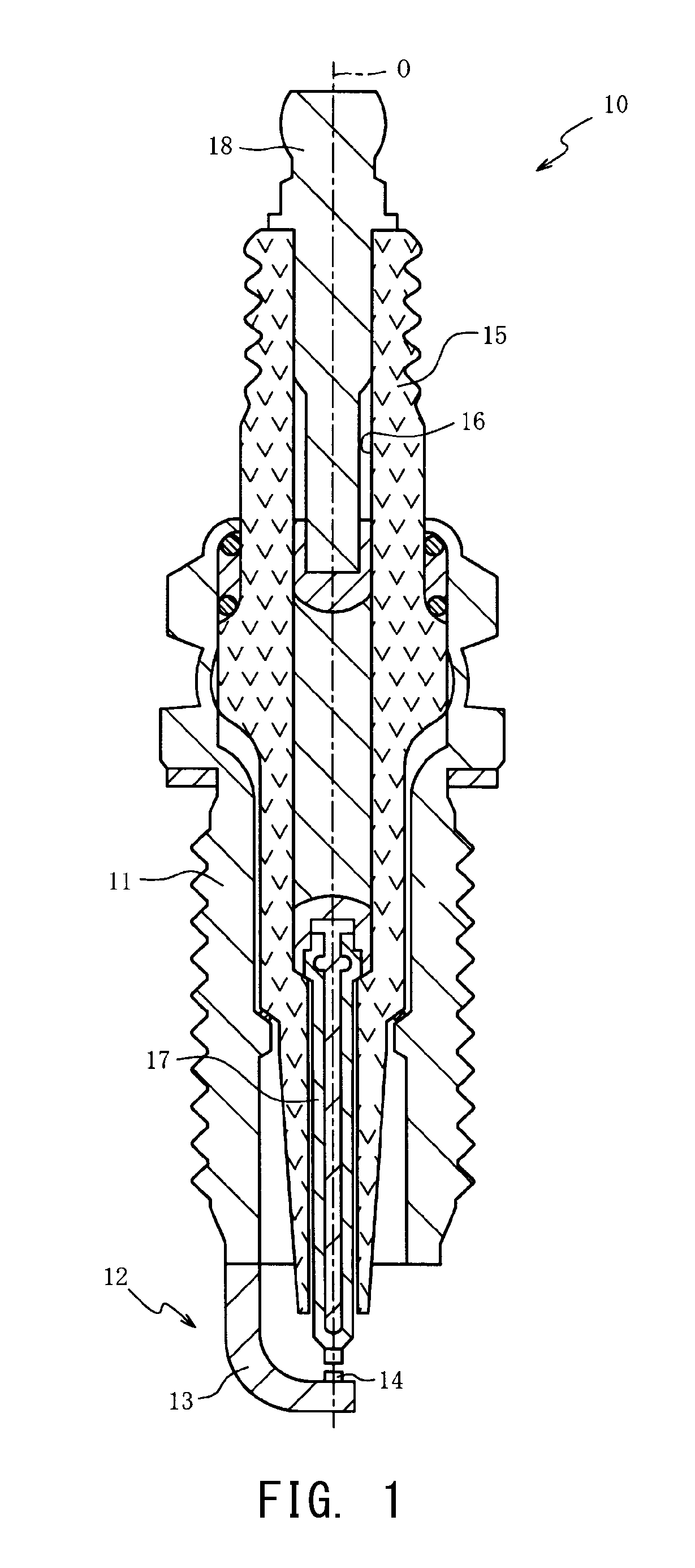
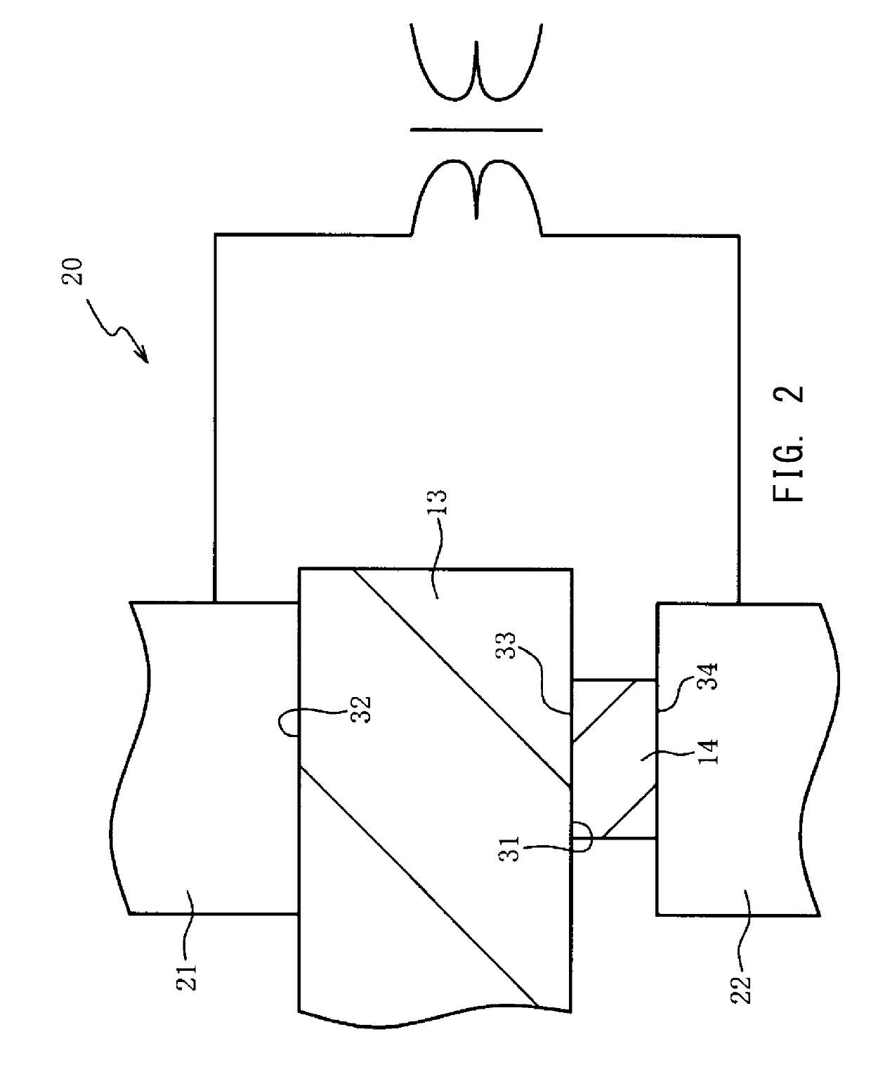
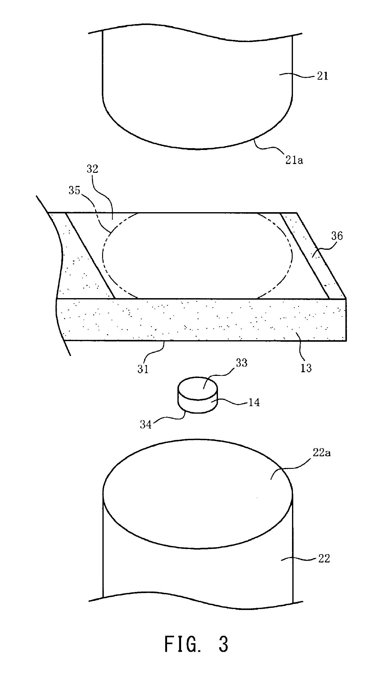
However, the above-described conventional technique has the following problem.

Method used


Image

  • Spark plug production method
  • Spark plug production method
  • Spark plug production method

Examples


example 1

[0035]30 rectangular plate-shaped electrode base materials each having a width of 2.7 mm and a thickness of 1.3 mm and 30 Cdisc-shaped tips each having a diameter of 1 mm and a thickness of 0.4 mm were prepared. Each electrode base material is formed from a nickel-based alloy, and each tip is formed from a platinum-nickel alloy. Dry type polishing was performed on a front surface and a rear surface of each electrode base material by means of a polishing belt, so that a rectangular-shaped first surface and a rectangular-shaped second surface each having a length of 6 mm and a width of 2.7 mm were produced on the front surface and the rear surface, respectively, of the electrode base material. Similarly, dry type polishing was performed on a front surface and a rear surface of each tip, so that a third surface and a fourth surface were produced on the front surface and the rear surface, respectively, of the tip.

[0036]Next, the arithmetic average roughness Ra of each of the first surfa...

example 2

[0046]As similar to Example 1, rectangular-shaped electrode base materials (each formed from a nickel-based alloy) each having a width of 2.7 mm and a thickness of 1.3 mm and disc-shaped tips (each formed from a platinum-nickel alloy) each having a diameter of 1 mm and a thickness of 0.4 mm were prepared. Dry type polishing was performed on the front surface and the rear surface of each electrode base material by means of the polishing disc, so that a rectangular-shaped first surface and a rectangular-shaped second surface each having a length of 6 mm and a width of 2.7 mm were produced on the front surface and the rear surface, respectively, of the electrode base material. Similarly, dry type polishing was performed on the front surface and the rear surface of each tip, so that a third surface and a fourth surface were produced on the front surface and the rear surface, respectively, of the tip.

[0047]The arithmetic average roughness Ra of each of the first surface and the second su...

example 3

[0051]As similar to Example 1, rectangular plate-shaped electrode base materials (each formed from a nickel-based alloy) each having a width of 2.7 mm and a thickness of 1.3 mm and disc-shaped tips (each formed from a platinum-nickel alloy) each having a diameter of 1 mm and a thickness of 0.4 mm were prepared. Dry type polishing was performed on the front surface and the rear surface of each electrode base material by means of the polishing disc, so that a rectangular-shaped first surface and a rectangular-shaped second surface each having a length of 6 mm and a width of 2.7 mm were produced on the front surface and the rear surface, respectively, of the electrode base material. Similarly, dry type polishing was performed on the front surface and the rear surface of each tip, so that a third surface and a fourth surface were produced on the front surface and the rear surface, respectively, of the tip.

[0052]The arithmetic average roughness Ra of each of the first surface and the sec...


PUM

PropertyMeasurementUnit
arithmetic average roughnessaaaaaaaaaa

Abstract

A method for manufacturing a spark plug. A first surface having an area larger than or equal to an area making contact with the tip is produced on the electrode base material by performing at least one of polishing and grinding thereon, and a second surface having an area larger than or equal to an area making contact with a first electrode is produced on the electrode base material by performing polishing or the like thereon. Resistance welding is performed by applying current between the first electrode and a second electrode, after the first surface of the electrode base material and the tip have been brought into contact with each other, the first electrode has been brought into contact with the second surface of the electrode base material, and the second electrode has been brought into contact with the tip.

Description

FIELD OF THE INVENTION[0001]The present invention relates to a method for manufacturing a spark plug and particularly relates to a method for manufacturing a spark plug such that variations in welding of an electrode base material and a tip can be suppressed.BACKGROUND OF THE INVENTION[0002]A spark plug is known which includes: a ground electrode in which a tip containing a noble metal is joined to an electrode base material; and a center electrode opposing the ground electrode with a spark gap therebetween. Resistance welding is one of the methods for joining the electrode base material and the tip together. Resistance welding is performed by applying current between the first electrode and the second electrode, in a state where the electrode base material and the tip stacked with each other are in contact with a first electrode and a second electrode, respectively. Japanese Patent Application Laid-Open (kokai) No. 2004-186152 discloses a technique in which the surface of the elect...

Claims


Application Information

Patent Timeline
Patent Type & Authority Applications(United States)
IPC IPC(8): H01T21/02H01T13/32
CPCH01T13/32H01T21/02
Inventor SHIMAMURA, TAKUYA
Owner NGK SPARK PLUG CO LTD
Why Eureka
Try Eureka