Imaging apparatus, imaging control method, and imaging control program

a technology of imaging control and control method, applied in the direction of exposure control, instruments, television systems, etc., can solve the problems of noisy image data obtained through imaging, visual undesirable, and inability to improve image quality, and achieve the effect of ensuring the dynamic rang

Inactive Publication Date: 2010-07-22
SONY CORP
View PDF10 Cites 14 Cited by
  • Summary
  • Abstract
  • Description
  • Claims
  • Application Information

AI Technical Summary

Benefits of technology

[0032]As described above, according to the invention, charges are read from an imaging device in non-light-shielded condition at each timing of dividing exposure time, then component corresponding to dark current component is removed from the imaging signal based on the read charges, then the digital imaging signal with the dark current component removed is accumulated sequentially for every reading and stored in a first memory, then, when exposure time ends, data corresponding to charges stored in the imaging device in light-shielded condition during the period of time corresponding to the exposure time is subtracted from the digital imaging signal stored in the first memory, and then the result of subtraction is output. This provides an advantage of preventing the data of accumulated digital imaging signal in the first memory from being clipped and ensuring the dynamic range.

Problems solved by technology

Under imaging conditions such as long exposure, increase in the number of white spots in the dark and increase in the signal level due to a fixed pattern of the imaging device may occur, which may cause image data obtained through imaging to be very noisy and visually undesirable.
When the signal level of a white spot caused by leak current is increased, by addition, to a level that exceeds memory word length, the information of the pixel with the white spot is clipped at the upper limit of dynamic range, which becomes a defect.
However, as described above, long exposure may cause many white spots, in which one white spot is likely adjacent to another white spot and then the interpolation using adjacent pixels may not improve image quality.

Method used


Image

  • Imaging apparatus, imaging control method, and imaging control program
  • Imaging apparatus, imaging control method, and imaging control program
  • Imaging apparatus, imaging control method, and imaging control program

Examples


Embodiment Construction

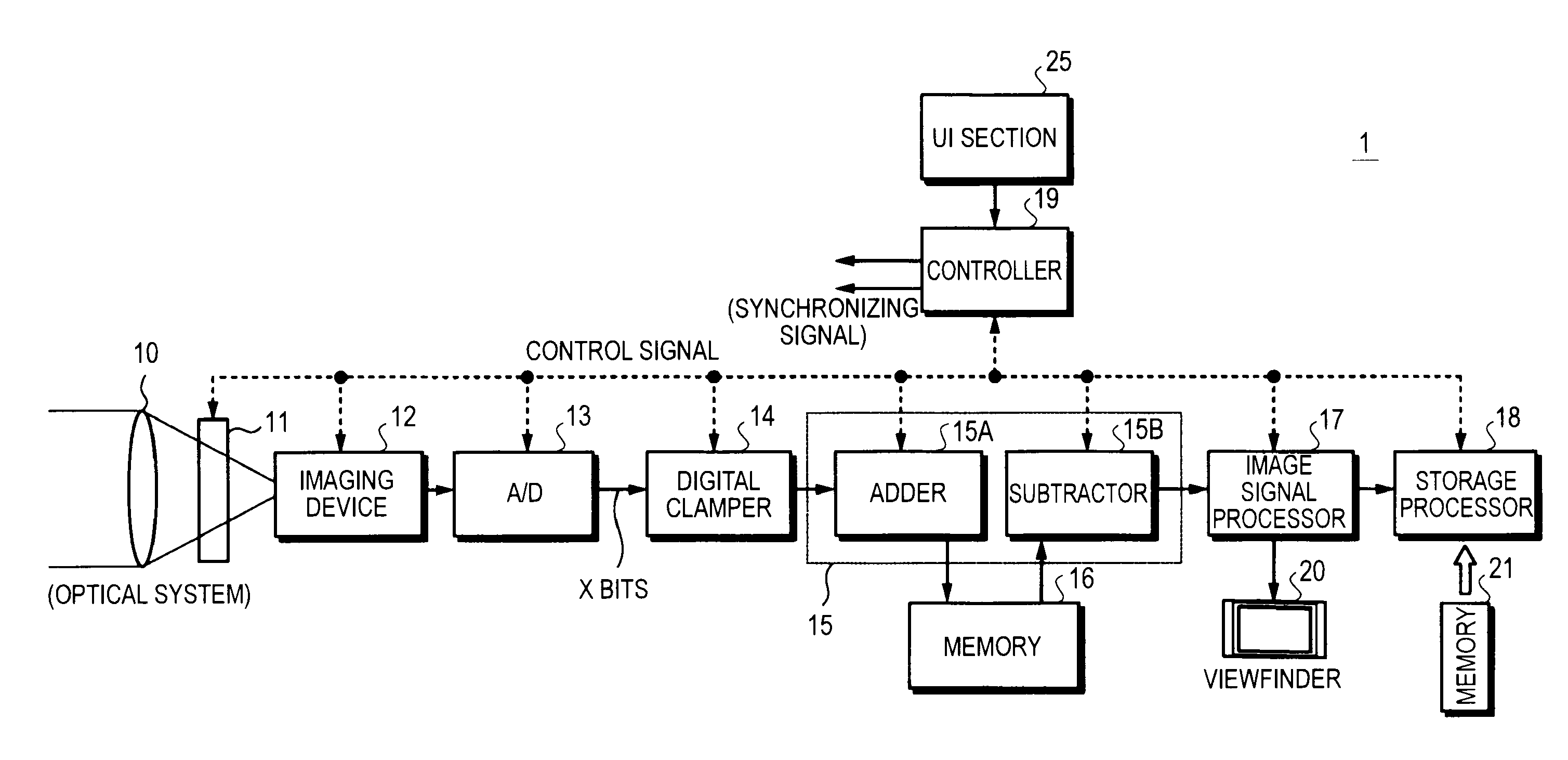
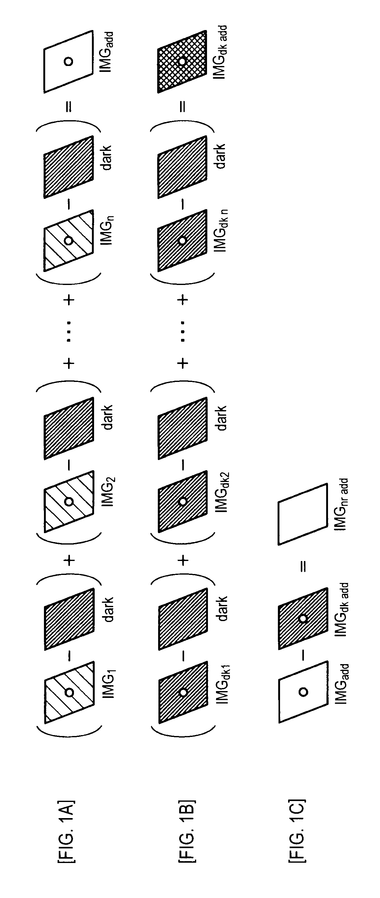
[0052]An embodiment of the invention is described below with reference to the drawings. FIG. 1 conceptually shows an exposure process in accordance with the invention. In the embodiment of the invention, first, with an imaging device irradiated with light from an object, the imaging device is exposed for divided exposure times (time-division exposure), then non-light-shielded image signals obtained through the time-division exposure are accumulated (see FIG. 1A). Next, with the imaging device shielded from light, the imaging device is exposed for divided exposure times (time-division exposure) in the same way, then light-shielded image signals obtained through the time-division exposure with the imaging device shielded from light are accumulated (see FIG. 1B). Finally, the imaging signal is obtained by subtracting the accumulated light-shielded image signal from the accumulated non-light-shielded image signal (see FIG. 1C).

[0053]Also, in the embodiment of the invention, signal compo...


PUM


Abstract

Imaging signal obtained through exposure for divided exposure times is A/D converted to digital imaging signal. Dark current component is subtracted from the digital imaging signal. The result of subtraction is accumulated and stored in a first memory. Next, exposure for divided exposure times is performed with the imaging device shielded from light. The obtained imaging signal is A/D converted to digital imaging signal. Dark current component is subtracted from the digital imaging signal. The result of subtraction is accumulated and stored sequentially in a second memory. The digital imaging signal stored in the second memory is subtracted from the digital imaging signal stored in the first memory. Then the result of subtraction is output. The word length allocated to one pixel in the first and second memories is longer than the word length of one A/D converted pixel.

Description

TECHNICAL FIELD[0001]The present invention relates to an imaging apparatus, imaging control method, and imaging control program suitable for long exposure imaging using an imaging device.BACKGROUND ART[0002]When imaging is performed with a film or imaging device of an imaging apparatus irradiated with a small amount of light per unit time, the imaging device or film needs to be irradiated with more amount of light by setting a long exposure time such as several tens of seconds, several minutes or longer. Examples of performing such imaging may include performing imaging in the dark, performing imaging on a dark object such as a star, and performing precise imaging with narrow aperture and deep depth of field.[0003]In imaging devices, such as CCD (charge coupled device) or CMOS (complementary metal-oxide semiconductor) imager, that convert irradiated light to electric signal by photoelectric conversion to output, imaging signals output with a predetermined period (such as frame rate)...

Claims


Application Information

Patent Timeline
Patent Type & Authority Applications(United States)
IPC IPC(8): H04N5/235G03B7/093H04N5/243H04N5/355H04N5/361H04N5/367
CPCH04N5/2355H04N5/35572H04N5/361H04N5/367H04N23/741H04N25/587H04N25/68H04N25/63
Inventor KITA, MITSUAKISATO, NOBUYUKIWAKATSUKI, MASASHIISHIBASHI, SHINYAMINAKUTI, JUNKOYAMA, TAKAHIRO
Owner SONY CORP
Why Eureka
Try Eureka