
Image display device

Active Publication Date: 2014-11-20
SAMSUNG DISPLAY CO LTD
View PDF0 Cites 13 Cited by
  • Summary
  • Abstract
  • Description
  • Claims
  • Application Information

AI Technical Summary

Benefits of technology

The patent describes a method and device for adjusting the saturation of an image signal. The method involves calculating the saturation of the image signal, setting a translation matrix based on the saturation, and performing a matrix calculation based on the translation matrix to adjust the saturation of the image. The device includes a saturation calculating unit, a matrix generating unit, and a data translation unit. The technical effect of the patent is to provide a more precise and accurate method for adjusting the saturation of an image signal, which can improve the quality of the displayed image.

Problems solved by technology

Consequently, inaccuracies may develop when attempting to display an image.

Method used


Image

  • Image display device
  • Image display device
  • Image display device

Examples


first embodiment

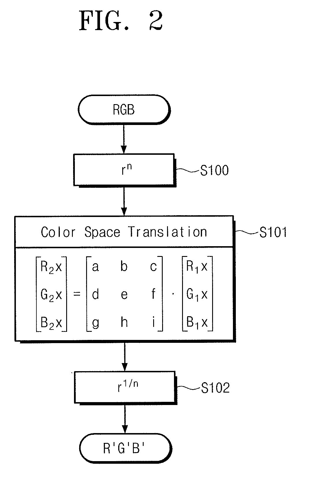
[0047]In a first embodiment, a translation matrix of f2( ) for the above-described color mapping is switched dynamically according to saturation (e.g., a distance S from the location of a white color) of a color of a translation target in a source gamut. Translation into a tone of a display gamut, where a tone difference at the source gamut decreases, may be made with respect to an area where the above-described saturation is low. As it approaches an area with high saturation, adjustment is made to correspond to a corner shape of the display gamut. Thus, it is possible to implement a dynamic range of the display gamut fully.

[0048]FIG. 3 illustrates an embodiment of a gamut adjusting circuit 1 included in an image display device. Referring to FIG. 3, gamut adjusting circuit 1 includes data translation unit 31, a saturation calculating unit 32, and a matrix generating unit 33. Input image signals R1x, G1x, and B1x are provided to data translation unit 31 and saturation calculating uni...

second embodiment

[0084]In a second embodiment, a source space is divided into six regions according to a color. Also, input parameters (e.g., a threshold value PL, a start translation matrix MSTART, and an end translation matrix MEND) about each region are defined independently. Thus, a gamut adjusting method may be provided with wider gamut or higher freedom.

[0085]FIG. 9 illustrates an embodiment of a gamut adjusting circuit. As shown in FIG. 9, a second embodiment is different from the first embodiment in that threshold values PL[R], PL[G], and PL[B] for primary colors are respectively provided, and a start translation matrix MSTART and a matrix interpolation step MSTEP are previously calculated and set by the primary color and by the complementary color. Thus, a hue area determining unit 34 may be included for calculating a hue area Hue_Area, not input image signals R1x, G1x, and B1x.

[0086]Also, there may be provided a parameter calculating unit 35 to select three types of input parameters (e.g....


PUM


Abstract

A gamut adjusting method fully expresses a dynamic range of a display gamut to display an image more naturally. With respect to a brightness signal of each primary color of an input image signal, a data translation unit executes a matrix calculation based on a translation matrix for conversion into an image signal for display control. A saturation calculating unit calculates saturation of the input image signal. When saturation is smaller than a threshold value, the data translation unit is set with a translation matrix such that a tone on the display corresponds to or approximates a tone of the input image signal. When saturation is greater than the threshold value and smaller than a maximum value, as the saturation increases, a translation matrix is switched such that a vector on a xy chromaticity diagram toward a tone on a display approximates a vector toward a tone for maximum saturation.

Description

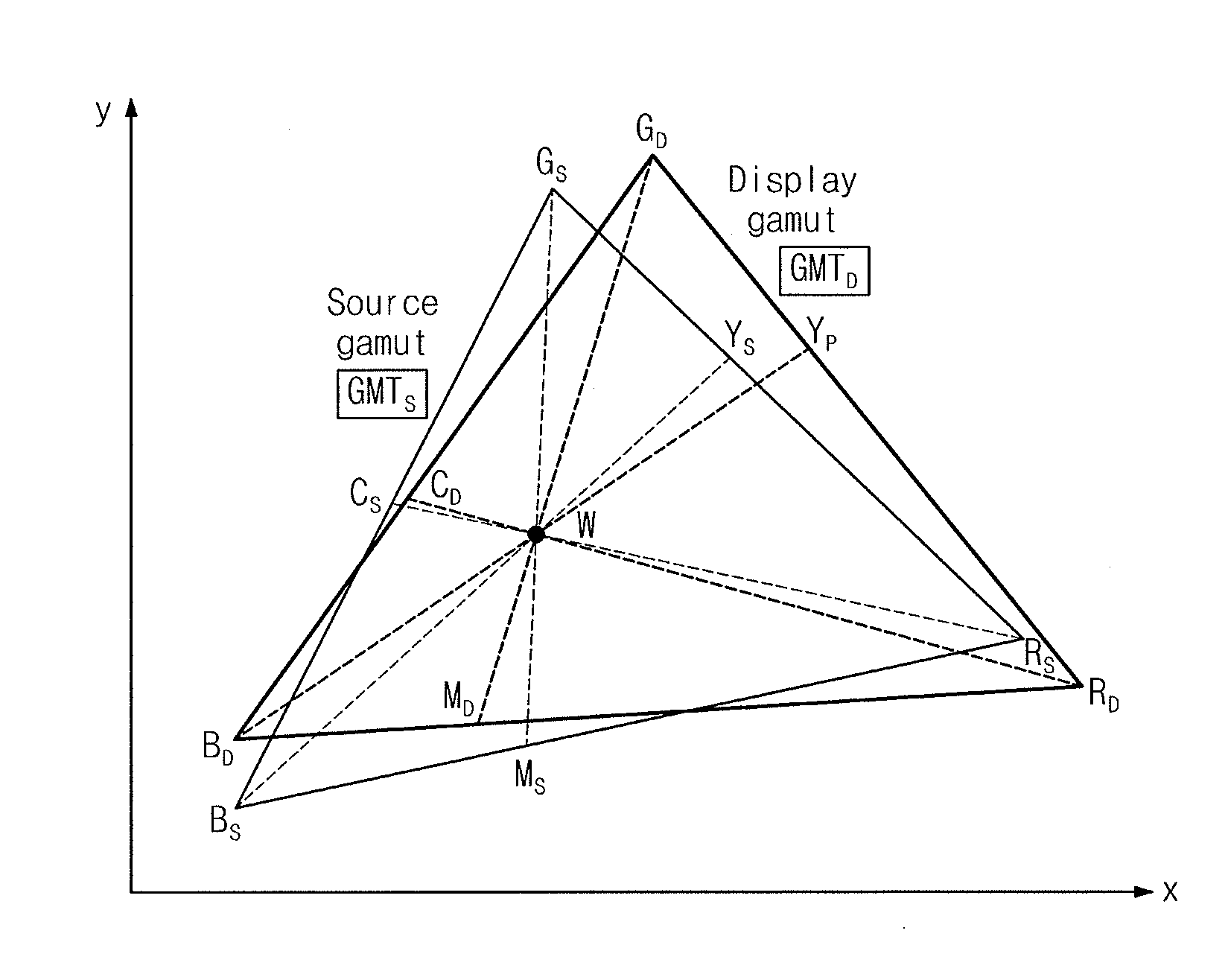
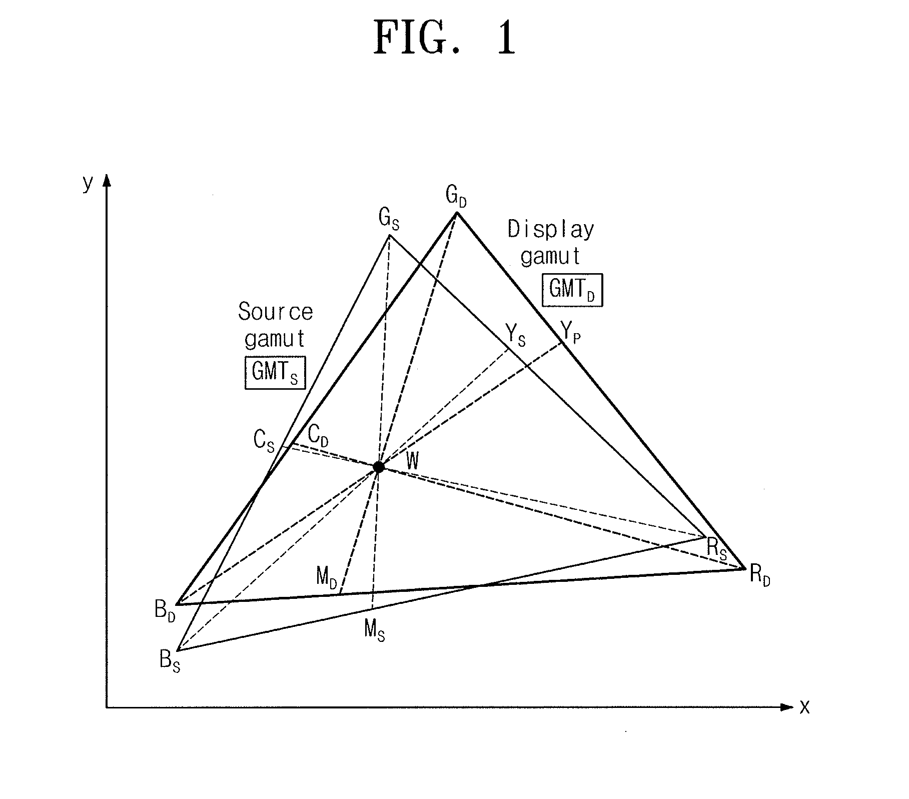
CROSS-REFERENCE TO RELATED APPLICATION[0001]Japanese Patent Application No. 2013-106554, filed on May 20, 2013, and entitled, “Image Display Device,” is incorporated by reference herein in its entirety.BACKGROUND[0002]1. Field[0003]One or more embodiments described herein relate to an image display device.[0004]2. Description of the Related Art[0005]Each image display device (or display) may have a unique gamut. The gamut may or may not correspond to standardized gamut (e.g., sRGB or NTSC) input image signal (source). Also, hues and saturations of colors may vary, and limits of saturation may differ for different display devices. Consequently, inaccuracies may develop when attempting to display an image.[0006]FIG. 1 illustrates an example of a chromaticity diagram of an XYZ color system which includes a display gamut (GMTD) and a source gamut (GMTS). The source gamut is a gamut standardized according to sRGB or NTSC.[0007]In general, it is possible to quadrate locations of white col...

Claims


Application Information

Patent Timeline
IPC IPC(8): G09G5/04
CPCG09G5/04G09G2340/06H04N9/67H04N1/6061G09G5/02
Inventor MATSUMOTO, KAZUHIRO
Owner SAMSUNG DISPLAY CO LTD
Learn More