
Low complexity multi-channel modulation method and apparatus

a multi-channel modulation and low-complex technology, applied in the field of multi-carrier modulation of digital data, can solve problems such as problems such as problems such as problems such as problems such as high par, clipping, and many mcm systems typically exhibit a large peak-to-average power ratio (par), and achieve high par signals in practical systems

Inactive Publication Date: 2011-01-25
THE UNIV OF SYDNEY +1
View PDF4 Cites 14 Cited by
  • Summary
  • Abstract
  • Description
  • Claims
  • Application Information

AI Technical Summary

Benefits of technology

The solution effectively reduces computational complexity and avoids clipping, achieving efficient digital communication by ensuring that all lattice points fall within a safe region, thereby improving bit-error rate and transmission efficiency.

Problems solved by technology

A problem that is encountered when implementing MCM schemes of the types described is that the time domain signals which result after the IFFT operation may exceed the linear range of the transmit amplifier so that clipping occurs.
A related problem is that many MCM systems typically exhibit a large peak-to-average power ratio (PAR).
Signals that exhibit a high PAR are problematical in practical systems because the digital-to-analog (DAC) and analog-to-digital converters (ADC) have only a finite range of voltages over which they can transmit and receive and only a finite resolution.
If the PAR is too high then either the signalling waveforms will be frequently clipped or there will be inadequate resolution when synthesized in the DAC or sampled in the ADC.
The computational overhead involved in implementing MCM of the prior-art type described is dominated by implementation of FFT / IFFT algorithms to decode and code symbols.

Method used


Image

  • Low complexity multi-channel modulation method and apparatus
  • Low complexity multi-channel modulation method and apparatus
  • Low complexity multi-channel modulation method and apparatus

Examples


Embodiment Construction

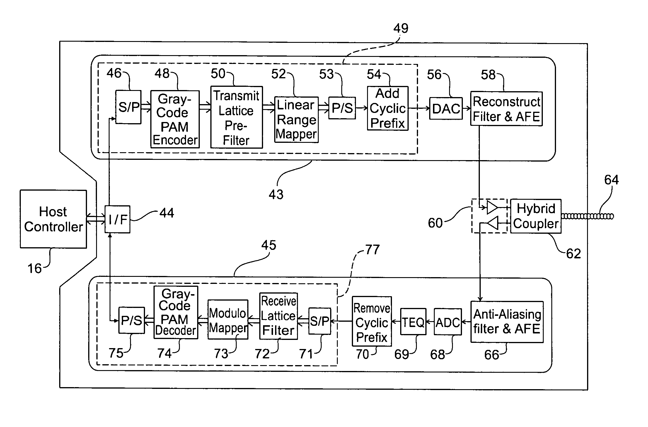
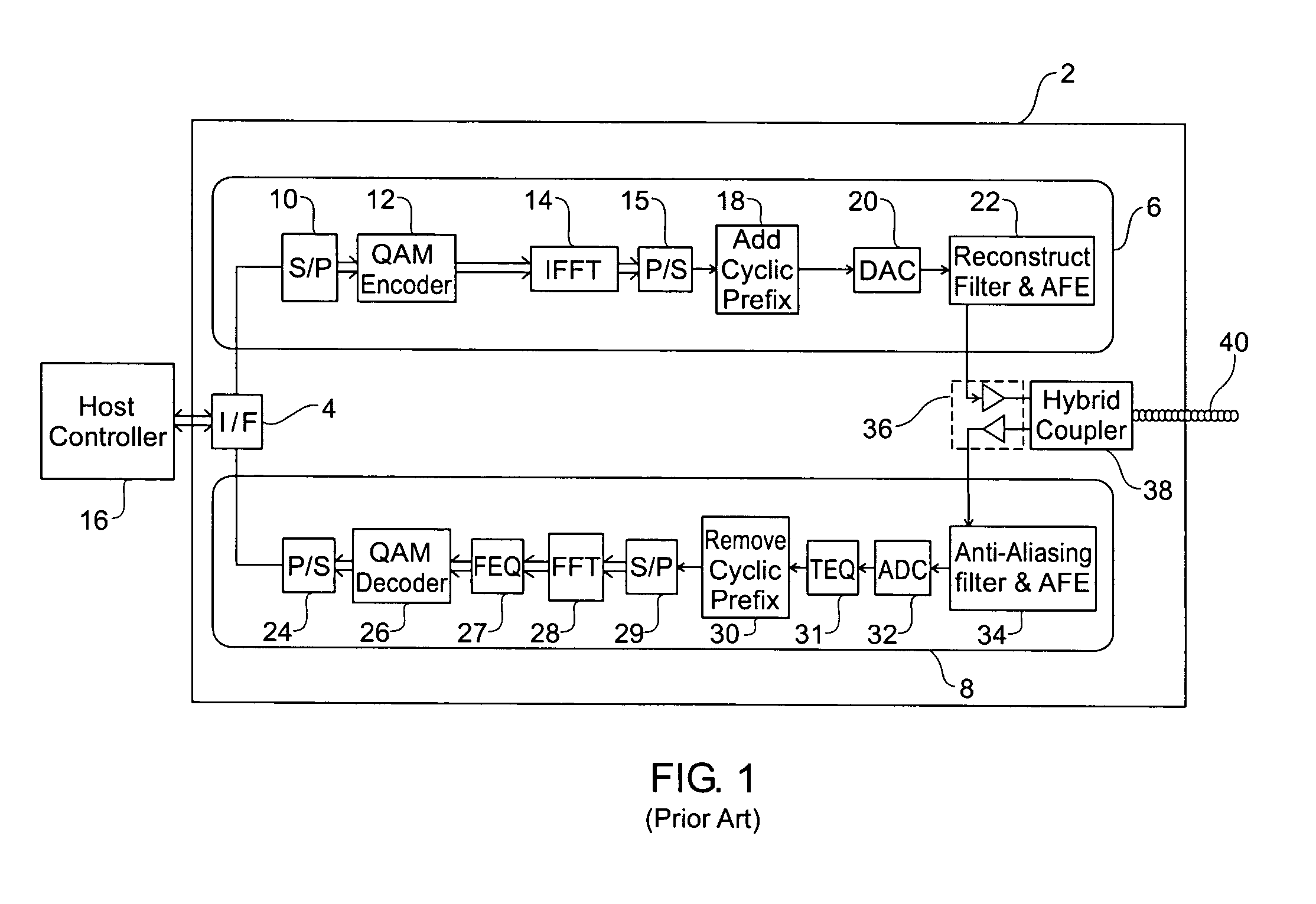
[0039]FIG. 1 is a schematic block diagram for explaining a basic prior-art discrete multi-tone modem 2 as used for asymmetric digital subscriber line (ADSL) communication. For purposes of explanation, FIG. 1 depicts a number of functional modules. It will be realised however that in practice an electronic processor executing a suitable firmware program stored in a memory device would implement many of the functional modules.

[0040]Modem 2 includes a digital interface 4 that facilitates digital transmission between a host controller 16 and transmitter 6 and receiver 8. For example the digital interface may perform an error correction function. Host controller 16 will typically comprise a personal computer or alternatively it could be a processor for controlling data traffic in an Internet service provider's central office. In use, modem 2 communicates with a remote modem across a channel comprised of conductor 40 that is typically a twisted pair of telephone wires.

[0041]Transmitter 6 ...


PUM


Abstract

A digital communications apparatus for processing a data vector includes a transmitter for communicating with a receiver across a channel having channel characteristics. A transmit vector is computed from the data vector and from values defining a basis for a transmit lattice. The transmit lattice defines a set of transmit symbols of length N and is related to an orthogonal receive lattice by the channel characteristics. The computation is performed according to an algorithm of order N complexity.

Description

[0001]This application claims priority under 35 U.S.C. §119(e)(1) of Provisional Application No. 60 / 479,499, filed Jun. 19, 2003.FIELD OF THE INVENTION[0002]The present invention relates to a method and apparatus for multi-carrier modulation of digital data. The invention particularly relates to a method and apparatus for multi-carrier modulation that is of relatively low computational complexity.BACKGROUND TO THE INVENTION[0003]Multi-carrier modulation (MCM) digital communication schemes, such as orthogonal frequency division modulation (OFDM) for wireless communication and discrete multitone (DMT) for digital subscriber lines (DSL) are being rapidly adopted in an effort to efficiently deliver high-speed data services. Such schemes make use of recent advances in digital signal processing (DSP) technology to replace many of the functions previously performed in analog circuitry, with more efficient and robust digital implementations.[0004]MCM is able to adequately overcome the effec...

Claims


Application Information

Patent Timeline
Patent Type & Authority Patents(United States)
IPC IPC(8): H04K1/10H04L12/26H04L27/26
CPCH04L27/2627H04L27/2649
Inventor CLARKSON, IAN VAUGHAN LYNDONCOLLINGS, IAIN BRUCE
Owner THE UNIV OF SYDNEY
Learn More