
Automatic audio gain control for concurrent capture applications

a technology of automatic audio gain control and concurrent capture, which is applied in the direction of gain control, electrical transducers, transducer casings/cabinets/supports, etc., can solve the problems of degrading the signal of the microphone, affecting the operation of the microphone, and requiring real-time feed from the microphon

Active Publication Date: 2012-10-16
MICROSOFT TECH LICENSING LLC
View PDF25 Cites 14 Cited by
  • Summary
  • Abstract
  • Description
  • Claims
  • Application Information

AI Technical Summary

Benefits of technology

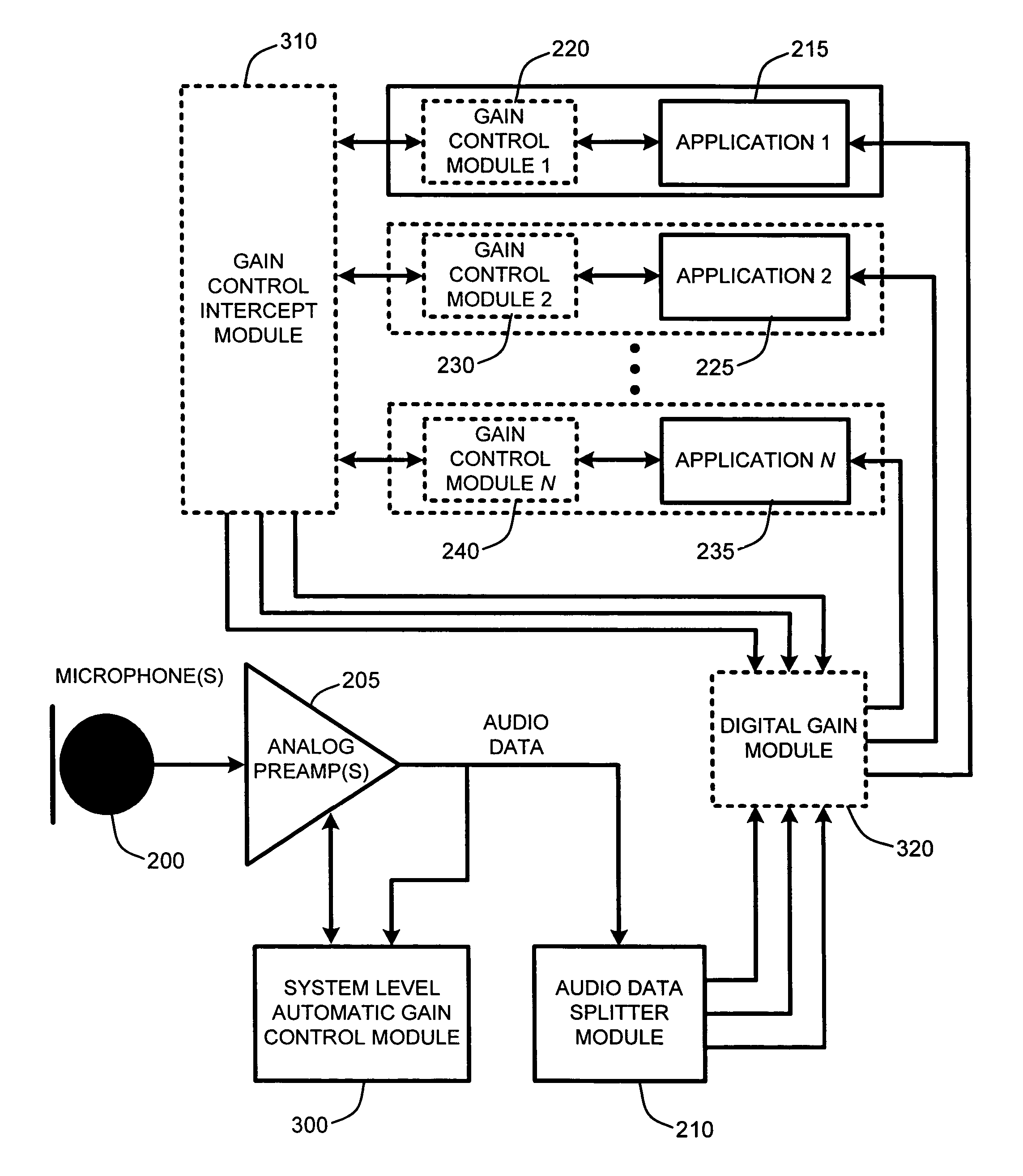
The patent describes a system and method for automatically controlling the gain of audio input from multiple applications running simultaneously on a device. The system uses a microphone or microphone array as the audio input source and aims to maximize the signal-to-noise ratio while preventing clipping of the desired speech signal. It also prevents individual applications from separately controlling the gain, which could lead to instability and quality degradation of other applications. The system uses an estimate of the background noise floor envelope to detect and prevent low-level background noise from affecting the audio capture. Overall, the system provides a unique solution for controlling audio input in a multi-application environment.

Problems solved by technology

Unfortunately, typical computing systems originally allowed only one application to capture data from a hardware device's microphone at any one time.
As a result, applications requiring real-time feed from a microphone were not typically capable of simultaneous operation.
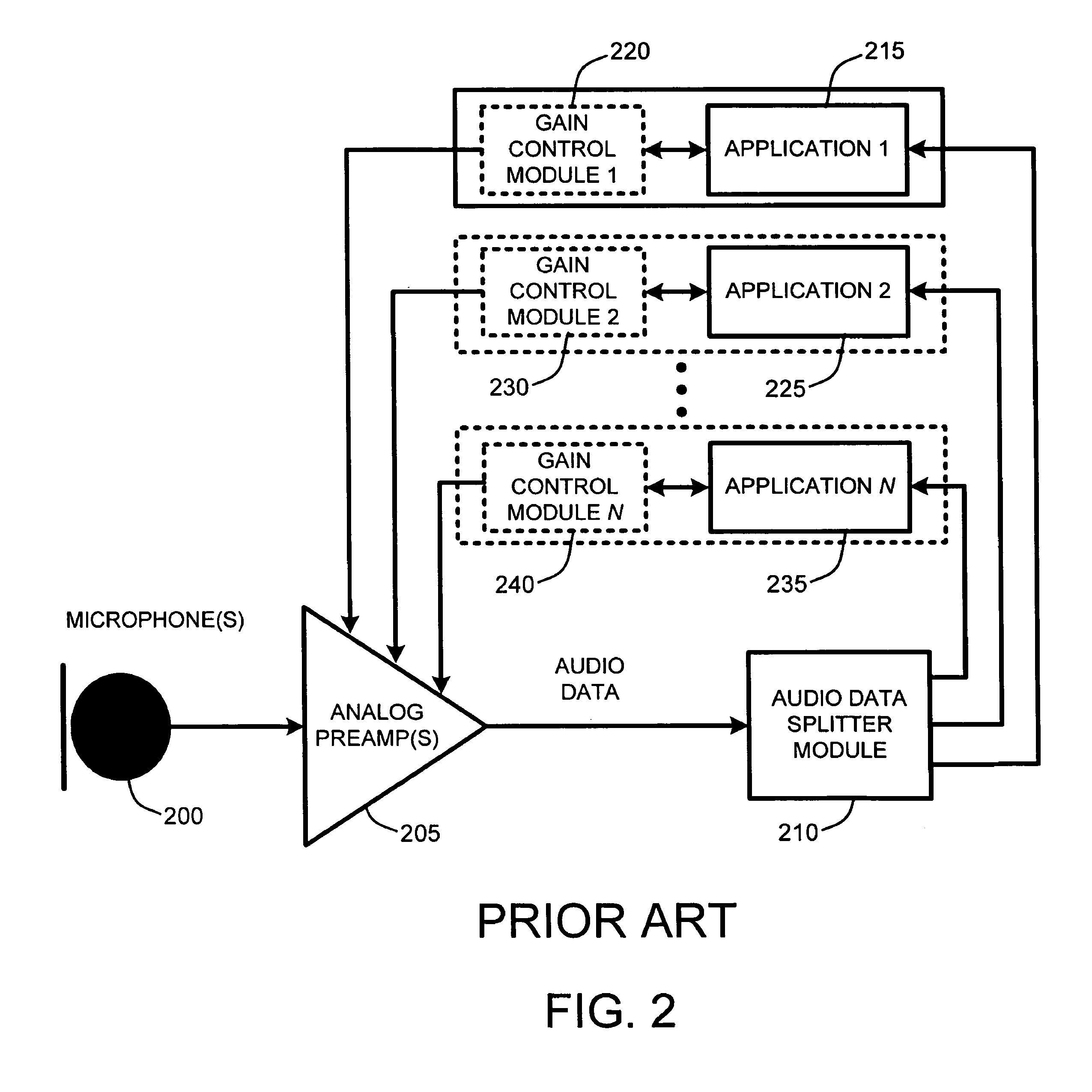
Unfortunately, while the new audio signal splitting feature provided by splitter.sys addressed the problem of being unable to simultaneously provide an audio input to two or more concurrent applications, it created a potential new problem for a number of applications that capture data from a microphone.
Consequently, if multiple capture applications are capturing data from a microphone, any two or more of those applications may be simultaneously attempting to control the microphone's analog gain, thereby likely degrading the microphone's signal.
This scenario often leads to oscillations of the microphone gain, which in the worst case, forces the analog microphone gain to either the minimum value or maximum value supported by the microphone's preamp because of the inherent instability of competing gain control systems.
Conversely, if the gain is forced to the maximum value, near end speech may be seriously distorted due to a significant amount of clipping.
As a result, many such applications are not capable of simultaneous operation without causing gain instability as a result of competing gain control systems.
Similar issues exist with respect to controlling gain of other audio inputs to a computing device, including any other analog audio source, such as, for example, CD audio and “line in” signals.
As a result, the applications continue to behave normally and are unaware that they are not actually controlling the microphone gain.

Method used


Image

  • Automatic audio gain control for concurrent capture applications
  • Automatic audio gain control for concurrent capture applications
  • Automatic audio gain control for concurrent capture applications

Examples


Embodiment Construction

[0026]In the following description of the preferred embodiments of the present invention, reference is made to the accompanying drawings, which form a part hereof, and in which is shown by way of illustration specific embodiments in which the invention may be practiced. It is understood that other embodiments may be utilized and structural changes may be made without departing from the scope of the present invention.

1.0 Exemplary Operating Environment:

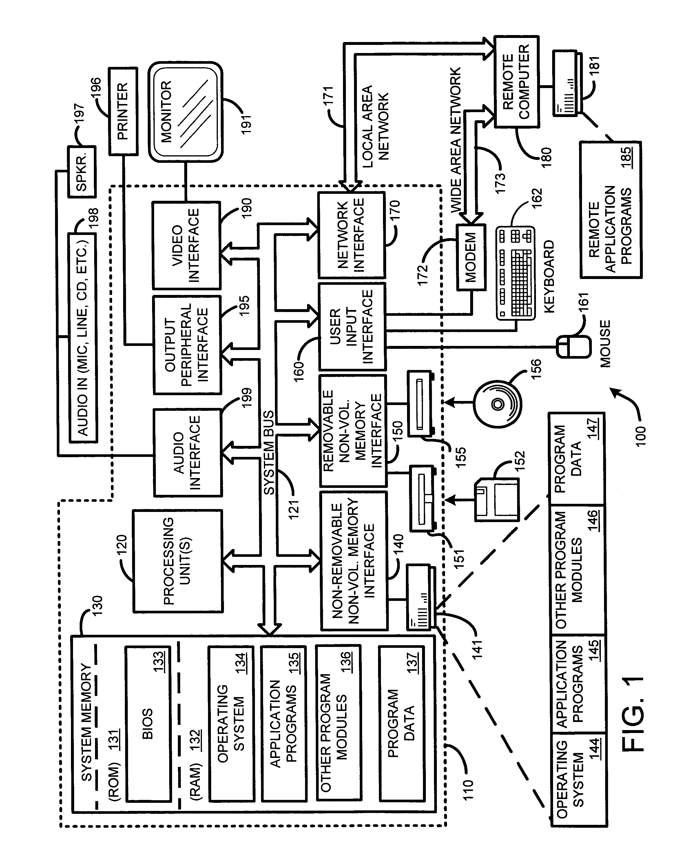
[0027]FIG. 1 illustrates an example of a suitable computing system environment 100 with which the invention may be implemented. The computing system environment 100 is only one example of a suitable computing environment and is not intended to suggest any limitation as to the scope of use or functionality of the invention. Neither should the computing environment 100 be interpreted as having any dependency or requirement relating to any one or combination of components illustrated in the exemplary operating environment 100.

[0028]The in...


PUM


Abstract

A system level automatic gain control (“System AGC”) automatically initializes and controls analog microphone gain in an environment where multiple independent applications simultaneously receive an input from a single analog microphone or microphone array. In one embodiment, the System AGC also prevents those applications from acting to separately control the gain by intercepting external gain control commands and responding to the corresponding application with a corresponding digital gain applied to the input signal from the microphone. Consequently, the System AGC avoids problems relating to oscillations and instability in the microphone gain resulting from multiple applications trying to simultaneously control the gain while preventing each application from adversely affecting the quality of another application's audio capture signal. Further, in one embodiment, the System AGC also acts to maximize the signal to noise (SNR) ratio of the microphone without introducing clipping as a function of a sampled background environment.

Description

BACKGROUND[0001]1. Technical Field[0002]The invention is related to audio input signal gain control, and in particular, to a system and method for providing an automatic system level gain control for allowing an audio signal, such as a microphone signal, “line in” audio signal, CD audio signal, etc., to be simultaneously provided to multiple separate audio capture or processing applications while providing a centralized gain control for each audio input source.[0003]2. Related Art[0004]Conventional analog microphones, including individual microphones and microphone array type devices, are well known to those skilled in the art. When connected to a computing device, such as a personal computer (PC) or the like, such microphones are frequently used in applications including, for example, voice over IP (VoIP) clients or speech recognition engines, which receive an audio signal captured by the microphone, and then process that signal in accordance with the application parameters.[0005]U...

Claims


Application Information

Patent Timeline
Patent Type & Authority Patents(United States)
IPC IPC(8): H03G3/00H03G9/00
CPCH03G3/301H03G3/3089H04R3/005H04R3/02H04R2410/00H04R2430/01
Inventor STOKES, III, JACK W.PLATT, JOHNSTEVENS, DAVID ALAN
Owner MICROSOFT TECH LICENSING LLC
Learn More