
Compound Barb Medical Device and Method

a medical device and compound technology, applied in the field of compound barb medical devices, can solve the problems of difficult or costly implementation of methods

Active Publication Date: 2010-08-19
TYCO HEALTHCARE GRP LP
View PDF102 Cites 64 Cited by
  • Summary
  • Abstract
  • Description
  • Claims
  • Application Information

AI Technical Summary

Benefits of technology

[0014]A method of forming a compound barb on a staple is also disclosed, including providing a staple having a pair of legs, each leg defining a longitudinal axis; and applying vibrational energy to a cutting element to form a compound barb on at least a portion of each leg including: forming a first cut in the leg, the first cut having a first ratio of cut depth to diameter of the leg; and forming a second cut in the leg, the second cut having a second ratio of cut depth to diameter of the leg.

Problems solved by technology

While various methods of forming barbs on sutures have been proposed, such methods may be difficult or costly to implement.
An anvil of a stapler generally crimps the staple, and thus, conventional staplers typically comprise complex structures which must not only eject the staples but to do so in a manner such that the staple deforms properly and timely.

Method used


Image

  • Compound Barb Medical Device and Method
  • Compound Barb Medical Device and Method
  • Compound Barb Medical Device and Method

Examples


Embodiment Construction

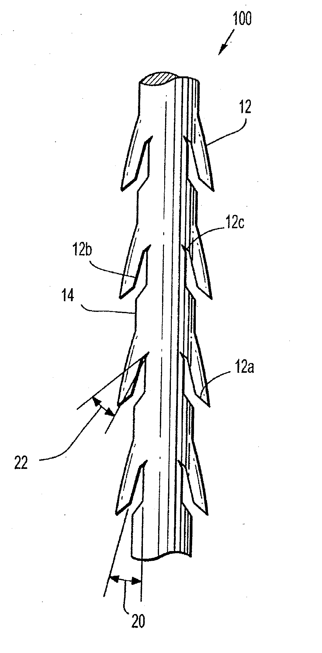
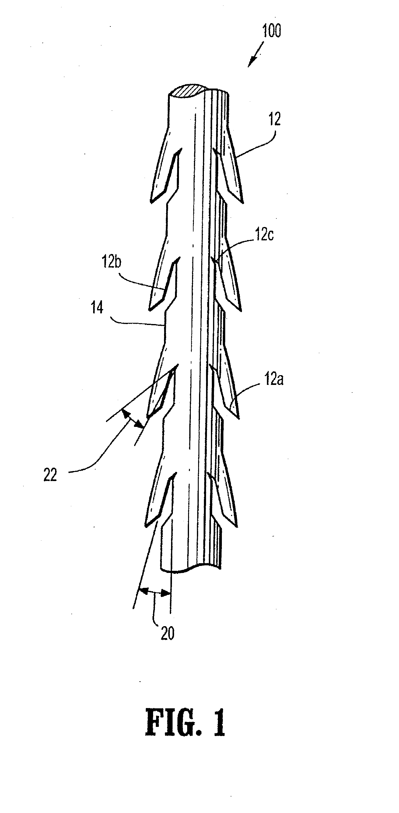
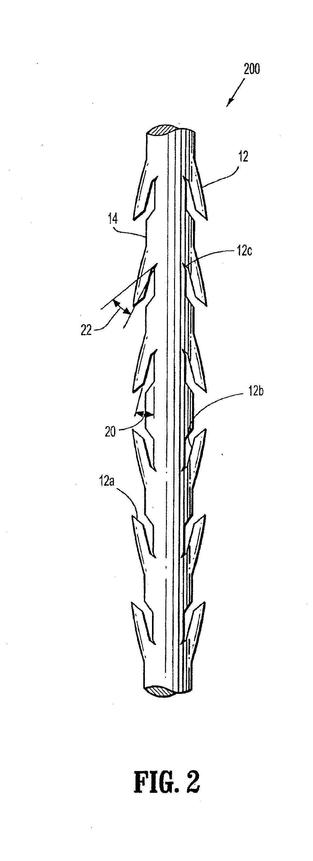
[0029]Referring in detail to the drawings in which like reference numerals are applied to like elements in the various views, FIG. 1 illustrates a medical device 100 having an elongated body 14 and at least one compound barb 12 extending from the elongated body 14. Compound barb 12 defines an inner surface which includes a first portion 12a disposed at a first orientation relative to the longitudinal axis of elongated body 14, a second portion 12b disposed at a second orientation relative to the longitudinal axis, and a third portion 12c disposed at a third orientation relative to the longitudinal axis.

[0030]Compound barbs 12 include at least one substantially linear portion. As illustrated in FIG. 1, first, second and third portions 12a-c are substantially linear. It is envisioned that at least one of the portions may be substantially non-linear, such as for example, arcuate as described hereinbelow.

[0031]As shown in the exemplary embodiment of FIG. 1, compound barbs 12 may be form...


PUM


Abstract

Barbed medical devices include a crown interconnecting a pair of legs and at least one barb extending from each of the legs. The at least one barb may define an inner surface with a first portion disposed at a first orientation relative to a longitudinal axis of the leg, a second portion disposed at a second orientation relative to the longitudinal axis, and optionally, a third portion disposed at a third orientation relative to the longitudinal axis of the leg.

Description

CROSS-REFERENCE TO RELATED APPLICATIONS[0001]This application is a continuation-in-part of U.S. patent application Ser. No. 12 / 361,962, filed Jan. 29, 2009, which claims the benefit of and priority to U.S. Provisional Application No. 61 / 029,964, filed Feb. 20, 2008, the entire disclosures of each of which are incorporated by reference herein.TECHNICAL FIELD[0002]The present disclosure relates generally to forming barbs on medical devices. In particular, the present disclosure relates to compound barb medical devices including shape memory polymeric materials, and methods of forming and using such medical devices.BACKGROUND OF RELATED ART[0003]Barbed sutures are known for use in medical procedures. The configuration of barbs on a barbed suture may be designed to optimize tissue holding for a particular indication. In some circumstances, a random configuration of barbs on the exterior surface of the suture may be preferred to achieve optimal wound closure. However, in other circumstan...

Claims


Application Information

Patent Timeline
Patent Type & Authority Applications(United States)
IPC IPC(8): A61B17/04B21G7/02
CPCA61B17/06166A61B17/064A61B2017/00004A61B2017/00867A61B2017/00893A61B2017/06176B21G7/02A61B2017/00526
Inventor HADBA, AHMAD ROBERTHODGKINSON, GERALDGLEIMAN, SETHCOHEN, MATTHEW D.MAIORINO, NICHOLASKOSA, TIMOTHY D.BUCHTER, MARK S.PRIMAVERA, MICHAEL
Owner TYCO HEALTHCARE GRP LP
Learn More