Hull robot steering system

a robot and steering system technology, applied in the field of steering systems, can solve the problems of unsatisfactory steering systems or complex steering systems with numerous moveable components, and achieve the effects of large turning radius, robust and simple design, and large turning radius

Active Publication Date: 2010-09-02
RAYTHEON CO
View PDF72 Cites 23 Cited by
  • Summary
  • Abstract
  • Description
  • Claims
  • Application Information

AI Technical Summary

Benefits of technology

[0006]If the steering angle of the drive system is very small, the resulting turning radius may be fairly large, but, since the hull of a ship is very large in area compared to the size of the robot, a large turning radius may be satisfactory. That realization enables the innovation of a drive system which can include relatively few moving parts and which is robust and simple in design. Alignment and adjustment of various components may not be required.

Problems solved by technology

Complex steering systems or steering systems with numerous moveable components are not desirable.

Method used


Image

  • Hull robot steering system
  • Hull robot steering system
  • Hull robot steering system

Examples


Embodiment Construction

[0042]Aside from the preferred embodiment or embodiments disclosed below, this invention is capable of other embodiments and of being practiced or being carried out in various ways. Thus, it is to be understood that the invention is not limited in its application to the details of construction and the arrangements of components set forth in the following description or illustrated in the drawings. If only one embodiment is described herein, the claims hereof are not to be limited to that embodiment. Moreover, the claims hereof are not to be read restrictively unless there is clear and convincing evidence manifesting a certain exclusion, restriction, or disclaimer.

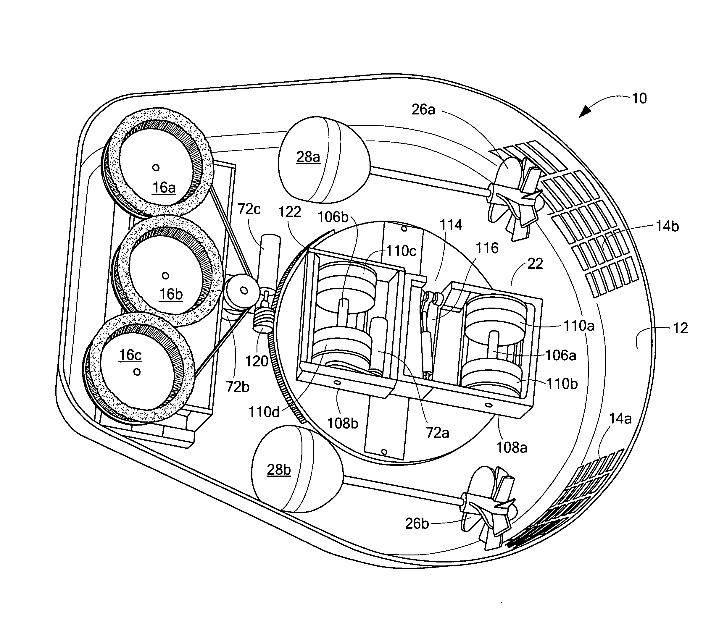
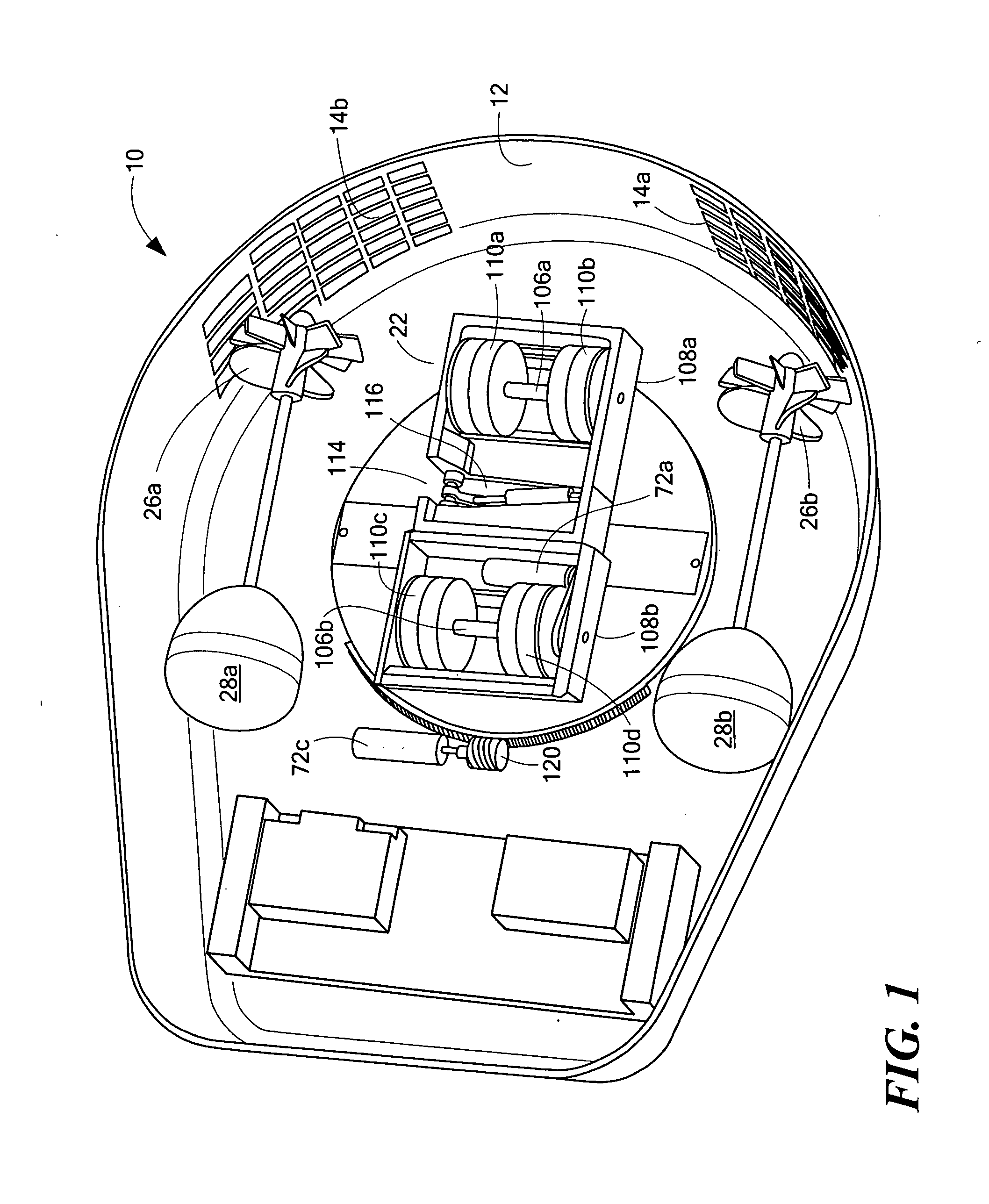
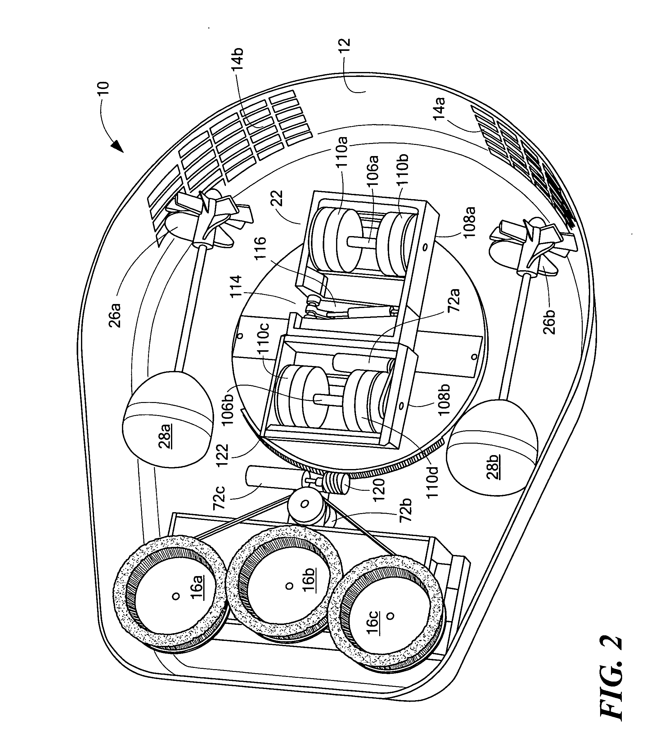
[0043]FIGS. 1-2 show robot 10 including robot body 12 with turbine intake vents 14a and 14b. Cleaning brushes 16a, 16b, and 16c are shown in FIG. 2. A magnetic drive system 22 is typically used to adhere the robot to the hull and to maneuver the robot about the hull.

[0044]In the examples shown, turbines 26a and 26b drive ge...


PUM


Abstract

A robot drive system preferably used for a vessel hull cleaning and/or inspection robot includes a first frame portion rotatably supporting a first axle with a first wheel thereon, and a second frame portion rotatably supporting a second axle with a second wheel thereon. A joint connects the first frame portion to the second frame portion and defines an expendable and contractible portion between the first frame portion and second frame portion. An actuator subsystem is configured expand and contract the expandable and contractible portion to move the first frame portion relative to the second frame portion at the joint to angle the first axle relative to the second axle to steer the robot.

Description

RELATED APPLICATIONS[0001]This application is a continuation-in-part application which claims the benefit of and priority to U.S. patent application Ser. No. 12 / 313,643, filed Nov. 21, 2008 under 35 U.S.C. §§119, 120, 363, 365, and 37 C.F.R. §1.55 and §1.78, incorporated herein by this reference. The subject application is related to U.S. patent application Ser. No. 12 / 583,346, filed Aug. 19, 2009 and U.S. patent application Ser. No. 12 / 587,949 filed Oct. 14, 2009.FIELD OF THE INVENTION[0002]The subject invention relates to a drive system, typically for a hull robot configured to clean and / or inspect the hull of a vessel.BACKGROUND OF THE INVENTION[0003]Co-pending U.S. patent application Ser. No. 12 / 313,643 filed Nov. 21, 2008 discloses a new autonomous hull robot including turbines driven by water flowing past the hull while the vessel is underway. The turbines operate (e.g., power) the cleaning and the drive subsystems of the robot.[0004]Most prior hull cleaning robots suffer from...

Claims


Application Information

Patent Timeline
Patent Type & Authority Applications(United States)
IPC IPC(8): B62D55/00B62D33/08
CPCB63B59/10B62D55/265
Inventor ROONEY, III, JAMES H.LONGLEY, JONATHAN T.ALLEN, SCOTT
Owner RAYTHEON CO
Why Eureka
Try Eureka