
Device and method for changing the stress-induced birefringence and/or the thickness of an optical component

a technology of stress-induced birefringence and optical component, which is applied in the direction of microlithography exposure apparatus, instruments, polarising elements, etc., can solve the problems of comparatively complicated arrangement, and achieve the effect of low space requirement and simple design

Inactive Publication Date: 2005-08-30
CARL ZEISS SMT GMBH
View PDF40 Cites 4 Cited by
  • Summary
  • Abstract
  • Description
  • Claims
  • Application Information

AI Technical Summary

Benefits of technology

[0009]It is therefore an object of the invention to create a device for changing the stress-induced birefringence and / or the thickness of an optical component, which device is of comparatively simple design and can manage with a very low space requirement.
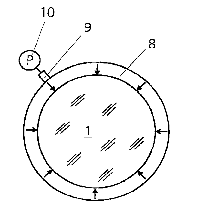
[0012]The optical component, which can be, for example, an end plate, a lens or, if appropriate, also a mirror, is gripped by the at least one clamping element at least approximately entirely such that there can be a very uniform injection of compressive stress into the optical component. The clamping element can be actuated via the at least one actuator, in order to raise the compressive stress applied to the optical component or, if appropriate, also to lower it.
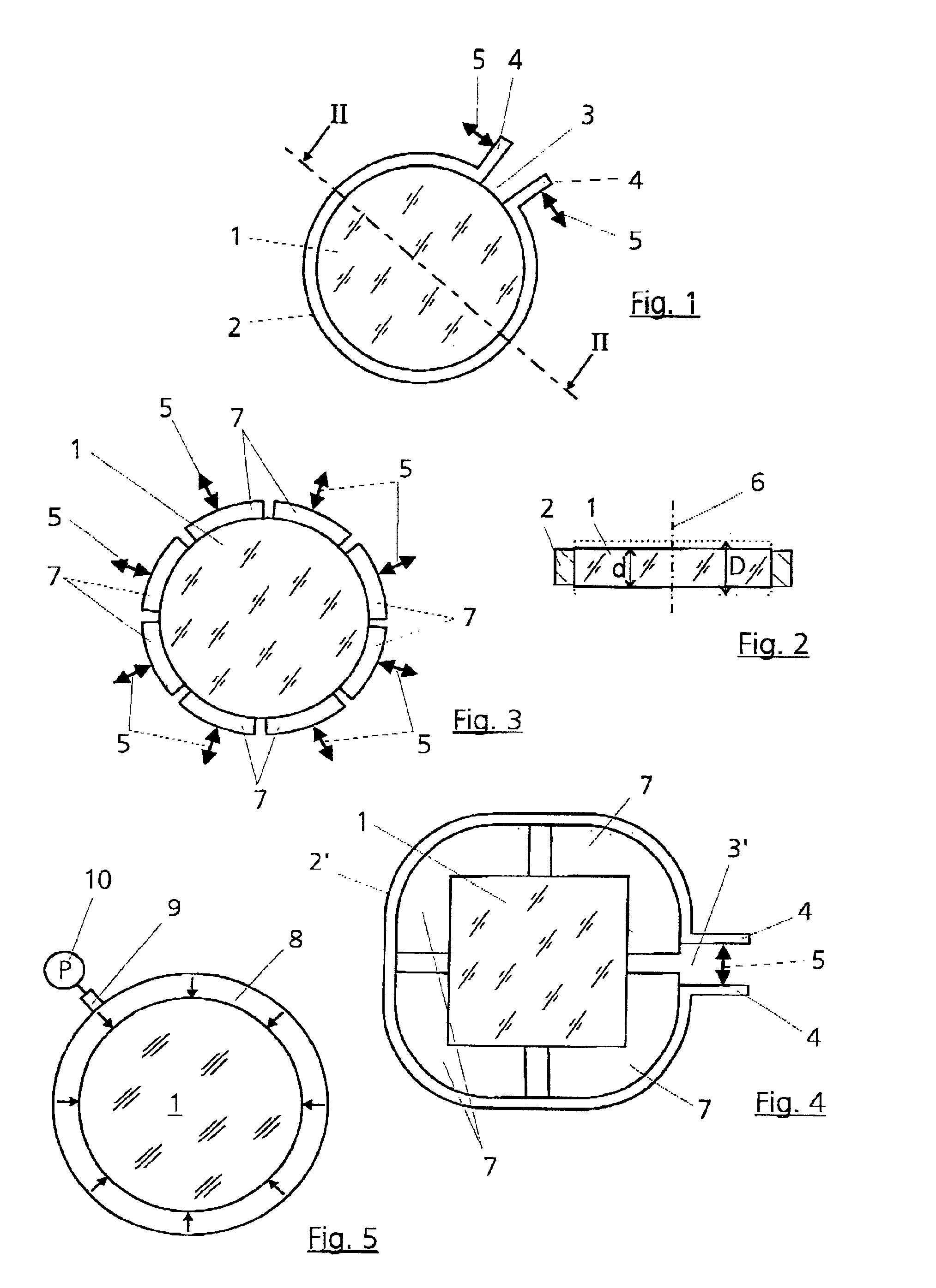
[0018]This open clamping ring surrounding the optical component creates a variant of the device according to the invention which is available, in particular, in the case of round or oval optical components that are appropriately gripped by the open clamping ring on the circumference aligned perpendicular to the optical axis. One clamping element, which can now be actuated with a single actuator, results in a very simple and robust design that, moreover, can also be executed very simply and in a space-saving fashion. In particular, the advantages with regard to the saving of overall space can be regarded as decisive advantages since, for example in the lenses in semiconductor lithography, the available overall space is frequently very tight and must therefore be utilized ideally.
[0020]By virtue of the fact that use is made here of compressive stresses instead of tensile stresses for the purpose of manipulation, it is possible largely to avoid a dangerous loading of the material of the optical component to which stress is applied. Since crystalline or amorphous materials are also frequently used for the corresponding optical components because said materials should have ideal properties with regard to the workability of their surface, it is frequently necessary to make compromises with regard to resistance to tensile stress. Consequently, a corresponding application of tensile stresses to these elements can lead to corresponding problems and a not inconsiderable loading of the material results, particularly when the change in the stress-induced birefringence and / or the thickness takes place as active control with many millions of control cycles. These loads can be minimized by the injection of compressive stress or, if appropriate, also the release of a compressive stress previously applied to the optical component in the neutral position of the latter, since the above-named materials are better suited by far to absorbing compressive stresses than to compensating tensile stresses applied to them.

Problems solved by technology

In this case, however, the arrangement is comparatively complicated, since it is necessary via appropriately complex structures to ensure uniform injection of the tensile stresses into the optical element, here the plane plate.

Method used


Image

  • Device and method for changing the stress-induced birefringence and/or the thickness of an optical component
  • Device and method for changing the stress-induced birefringence and/or the thickness of an optical component

Examples


Embodiment Construction

[0028]FIG. 1 shows an optical component 1 that is gripped by a clamping element 2 that is designed here as an open clamping ring 2. The clamping ring 2 has an opening 3 in its circumference such that the portion of the circumference of the optical component 1 gripped by the clamping ring 2 is smaller than 0.2 times the total circumference of the optical component 1. Fitted in the region of this opening 3 are two lugs 4 on which at least one actuator 5, indicated here by two double arrows 5, acts.

[0029]Ideally, in the case of a real structure, there is arranged in the region of the opening 3 an actuator 5 that moves the two lugs 4 of the clamping element in such a way that the size of the opening 3, and thus the portion of the circumference of the optical component 1 gripped by the clamping ring 2, can be changed by the actuator 5. All current forms of actuators 5 can be used as actuators 5 for such a design, and these would include pneumatic or hydraulic force elements, spindle / moto...


PUM


Abstract

A device serves the purpose of changing the stress-induced birefringence and / or the thickness (d and D, respectively) of an optical component by elastic deformation caused by means of stress. The optical component is gripped on a circumference, arranged at least approximately perpendicular to the optical axis, at least approximately entirely by at least one clamping element. The at least one clamping element can be actuated by at least one actuator.In the case of a method for this purpose, compressive stress is applied to the optical component, the elastic deformation being varied via a variation in the compressive stress.

Description

BACKGROUND OF THE INVENTION[0001]1. Field of the Invention[0002]The invention relates to a device for changing the stress-induced birefringence or the thickness or the stress-induced birefringence and the thickness of an optical component by elastic deformation caused by means of stress.[0003]The invention relates also to a method for changing the stress-induced birefringence or the thickness or the stress-induced birefringence and the thickness of an optical component by elastic deformation caused by means of stress.[0004]2. Description of the Related Art[0005]It is known from the general specialist literature (for example Bergmann Schäfer; Volume 3—Optik; 9th edition 1993; deGryther; Chapter 4, Point 13 “Induzierte Doppelbrechung in isotropen Stoffen” [“Induced birefringence in isotropic materials”]) that it is possible by injecting pressure or tensile stresses which respectively effect at least small plastic deformations in the material to vary correspondingly the stress-induced ...

Claims


Application Information

Patent Timeline
IPC IPC(8): G02B26/00G02B5/30G03F7/20
CPCG02B5/3083G02B26/00G03F7/708Y10S359/90
Inventor LABUS, RAINER
Owner CARL ZEISS SMT GMBH
Learn More