Direct smelting vessel and cooler therefor

a technology of smelting vessel and cooler, which is applied in the direction of manufacturing converters, furnace cooling, blast furnace components, etc., can solve the problems of refractory erosion of the upper part of the hearth, and achieve the effect of simple and robust design

Active Publication Date: 2010-02-25
TATA STEEL
View PDF6 Cites 4 Cited by
  • Summary
  • Abstract
  • Description
  • Claims
  • Application Information

AI Technical Summary

Benefits of technology

[0060]The use of water cooled side walls enables a simple and robust design utilising vertical, preferably flat, side walls that are substantially free of interlocking or other sealing between adjacent elements that might other

Problems solved by technology

The HIsmelt Process is turbulent and this results in refractory erosion of the upper part of the hearth due to chemical attack and p

Method used


Image

  • Direct smelting vessel and cooler therefor
  • Direct smelting vessel and cooler therefor
  • Direct smelting vessel and cooler therefor

Examples


Embodiment Construction

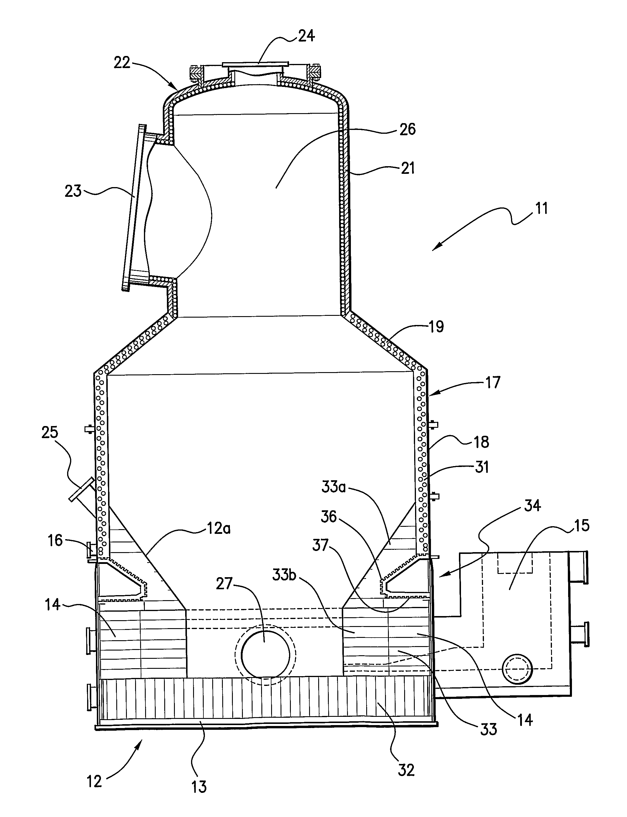
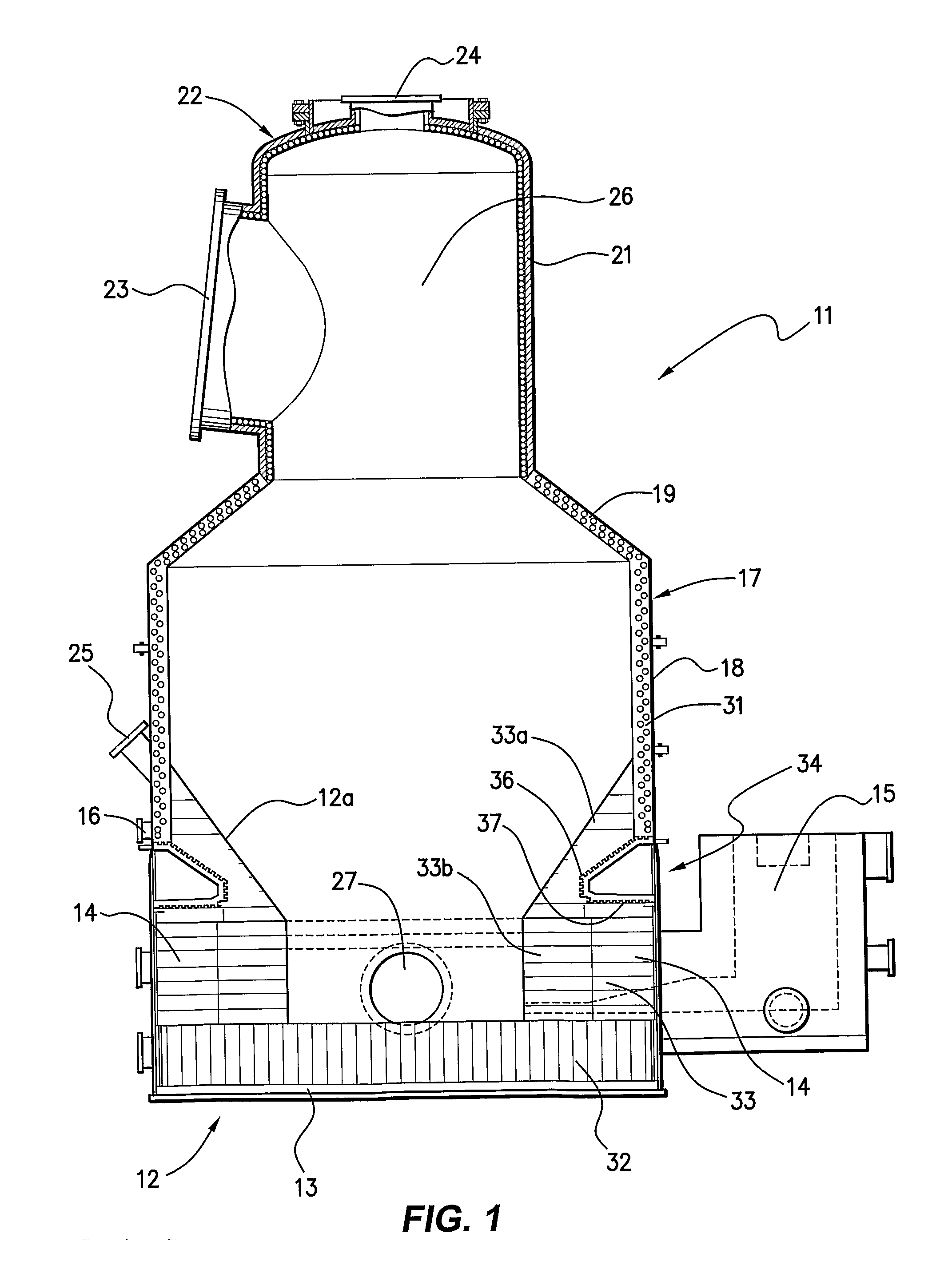
[0074]FIGS. 1 to 6 of the drawings illustrate a direct smelting vessel suitable for operation of the HIsmelt process as described in U.S. Pat. No. 6,267,799 and International Patent Publication WO 96 / 31627. The metallurgical vessel is denoted generally as 11 and has a hearth 12 which includes a base 13 and sides 14 formed of refractory bricks, a forehearth 15 for discharging molten metal continuously and a tap hole 16 for discharging molten slag.

[0075]The base of the vessel is fixed to the bottom end of an outer vessel shell 17 made of steel and comprises a cylindrical main barrel section 18, an upwardly and inwardly tapering roof section 19, and an upper cylindrical section 21 and lid section 22 defining an offgas chamber 26. Upper cylindrical section 21 is provided with a large diameter outlet 23 for offgases and the lid 22 has an opening 24 in which to mount a downwardly extending gas injection lance (not shown) for delivering a hot air blast into the upper region of the vessel. ...


PUM

PropertyMeasurementUnit
Lengthaaaaaaaaaa
Lengthaaaaaaaaaa
Lengthaaaaaaaaaa

Abstract

A direct smelting vessel and a hearth cooler element are disclosed. The vessel includes a refractory lined hearth. An inner surface of an upper part of the hearth extends upwardly and outwardly to side walls of the vessel. The upper part of the hearth incorporates a hearth cooler disposed outwardly behind the refractory lining of that part of the hearth and below the cooling panels on the side walls of the vessel. The hearth cooler comprises a plurality of cooler elements. Each cooler element has a hollow open-backed shell structure having base, top and side walls formed integrally in a cast structure and incorporating coolant flow passages.

Description

TECHNICAL FIELD[0001]The present invention relates to vessels used for performing direct smelting to produce molten metal in pure or alloy form from a metalliferous feed material such as ores, partly reduced ores and metal-containing waste streams.[0002]The present invention relates more particularly to coolers used as a part of the vessels[0003]A known direct smelting process, which relies on a molten metal layer as a reaction medium, and is generally referred to as the HIsmelt process, is described in U.S. Pat. No. 6,267,799 and International Patent Publication WO 96 / 31627 in the name of the applicant. The HIsmelt process for producing molten iron as described in these publications comprises:[0004](a) forming a bath of molten iron and slag in a vessel;[0005](b) injecting into the bath:[0006](i) a metalliferous feed material, typically metal oxides; and[0007](ii) a solid carbonaceous material, typically coal, which acts as a reductant of the metal oxides and a source of energy; and...

Claims


Application Information

Patent Timeline
IPC IPC(8): C21C5/46C21C5/42C21B13/10C21B7/10
CPCF27B3/24F27D1/12F27D9/00F27B3/16C21C5/56F27B1/24C21B13/10Y02P10/134C21C5/46C21B7/10C21C5/42
Inventor MEDINA, HECTOR
Owner TATA STEEL
Why Eureka
Try Eureka