Detection device comprising an improved cold finger

a detection device and cold finger technology, applied in solid-state devices, radiation pyrometry, optical radiation measurement, etc., can solve the problems of insufficient rigidity to prevent deformation, difficult implementation of the structure, and insufficient rigidity of the device, etc., to achieve simple and robust design, enhance thermal performance

Active Publication Date: 2016-10-11
LYNRED +1
View PDF16 Cites 2 Cited by
  • Summary
  • Abstract
  • Description
  • Claims
  • Application Information

AI Technical Summary

Benefits of technology

[0011]It is observed that a requirement exists to provide a detection device that presents enhanced thermal performances while at the same time preserving a simple and robust design. Another of the objects of the invention is to propose a detection device in which the thermal losses are reduced to the minimum.

Problems solved by technology

However this architecture is difficult to implement and the final performances of the device are not satisfactory.
However, it has been observed that if the walls of the cold finger are too thin, they are no longer sufficiently rigid to prevent deformation of the cold finger during operation of the latter.
This deformation of the cold finger results in a considerable loss of the optic performances of the detection device.

Method used


Image

  • Detection device comprising an improved cold finger
  • Detection device comprising an improved cold finger
  • Detection device comprising an improved cold finger

Examples


Embodiment Construction

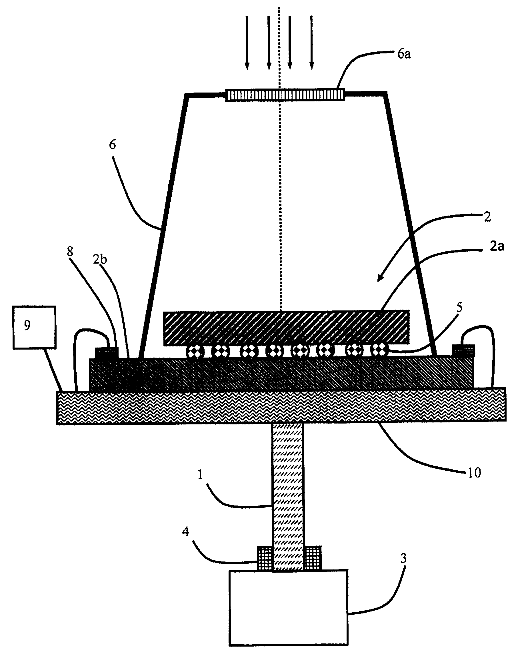
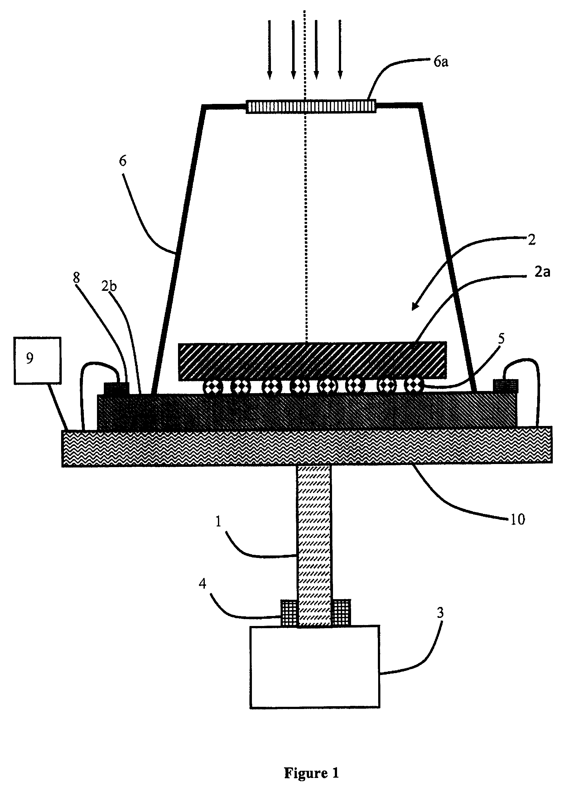
[0020]FIG. 1 schematically represents a cold finger 1 of a cooled detection device. Cold finger 1 comprises a hollow part of elongated shape. Cold finger 1 is preferably cylindrical in shape and in revolution. Cold finger 1 is designed to connect a detector 2 with a cooling system 3. One end of finger 1 is in contact with the area to be cooled, here the detector, and the other end is in contact with cooling system 3 which is at a higher temperature. A temperature gradient exists along cold finger 1.

[0021]This configuration ensures thermal insulation between the top part of the cold finger, for example at cryogenic temperature, and the bottom part of the cold finger which is at a higher temperature, for example at ambient temperature.

[0022]Cold finger 1 comprises at least one side wall which forms the sides of the finger. The sides of the cold finger can be broken down into one side wall or several side walls. Cold finger 1 advantageously comprises a top which closes cold finger 1, b...


PUM

PropertyMeasurementUnit
thicknessaaaaaaaaaa
diameteraaaaaaaaaa
heightaaaaaaaaaa

Abstract

The detection device comprises a cold finger which performs the thermal connection between a detector and a cooling system. The cold finger comprises at least one side wall at least partially formed by an area made from the amorphous metal alloy. Advantageously, the whole of the cold finger is made from the amorphous metal alloy.

Description

BACKGROUND OF THE INVENTION[0001]The invention relates to a detection device comprising a cold finger forming a cooling support of an infrared detector.STATE OF THE ART[0002]In the field of detection devices, there is commonly a photodetector associated with a readout circuit. The photodetector delivers a signal representative of the observed scene and this signal is treated by the readout circuit.[0003]Biasing of the photodetector is obtained by means of a substrate potential imposed on a first terminal of the photodetector and by means of a reference potential imposed on the second terminal of the photodetector. The reference potential is imposed by a read device of capacitive transimpedance amplifier type.[0004]In order to obtain high detection performances, it is advantageous to use particular substrates, for example made from Mercury, Cadmium, Tellurium and to make this equipment operate at low temperature. The use of a low temperature enables stray electric disturbances to be ...

Claims


Application Information

Patent Timeline
Patent Type & Authority Patents(United States)
IPC IPC(8): G01J5/02H01L31/103H01L31/02H01L31/024G01J5/06H01L31/0232C22C45/10C22C45/00
CPCG01J5/061H01L31/024H01L31/02016H01L31/02325H01L31/1032C22C45/003C22C45/008C22C45/10H01L2224/16145H01L2224/48091H01L2924/00014C22C5/04C22C16/00C22C19/07C22C38/002C22C38/005C22C38/08C22C38/10C22C38/22C22C38/30C22C38/32C22C38/36C22C38/38C22C38/54H01L27/1443
Inventor CASSAIGNE, PIERRELENAIN, ALEXISGRAVIER, SEBASTIENKAPELSKI, GEORGES
Owner LYNRED
Why Eureka
Try Eureka