Sealing portion of wellbore

A wellbore, positioned technology, applied in the directions of sealing/packing, wellbore/well components, production fluid, etc., can solve the problems of drilling rig loss, inability to provide technical solutions, etc.

Active Publication Date: 2018-04-17
SAUDI ARABIAN OIL CO
View PDF7 Cites 2 Cited by
  • Summary
  • Abstract
  • Description
  • Claims
  • Application Information

AI Technical Summary

Problems solved by technology

This can result in days to weeks of lost time for rigs
However, conventional liner hanger systems do not provide any effective remedial options based on technical solutions after equipment failure

Method used


Image

  • Sealing portion of wellbore
  • Sealing portion of wellbore
  • Sealing portion of wellbore

Examples


Embodiment Construction

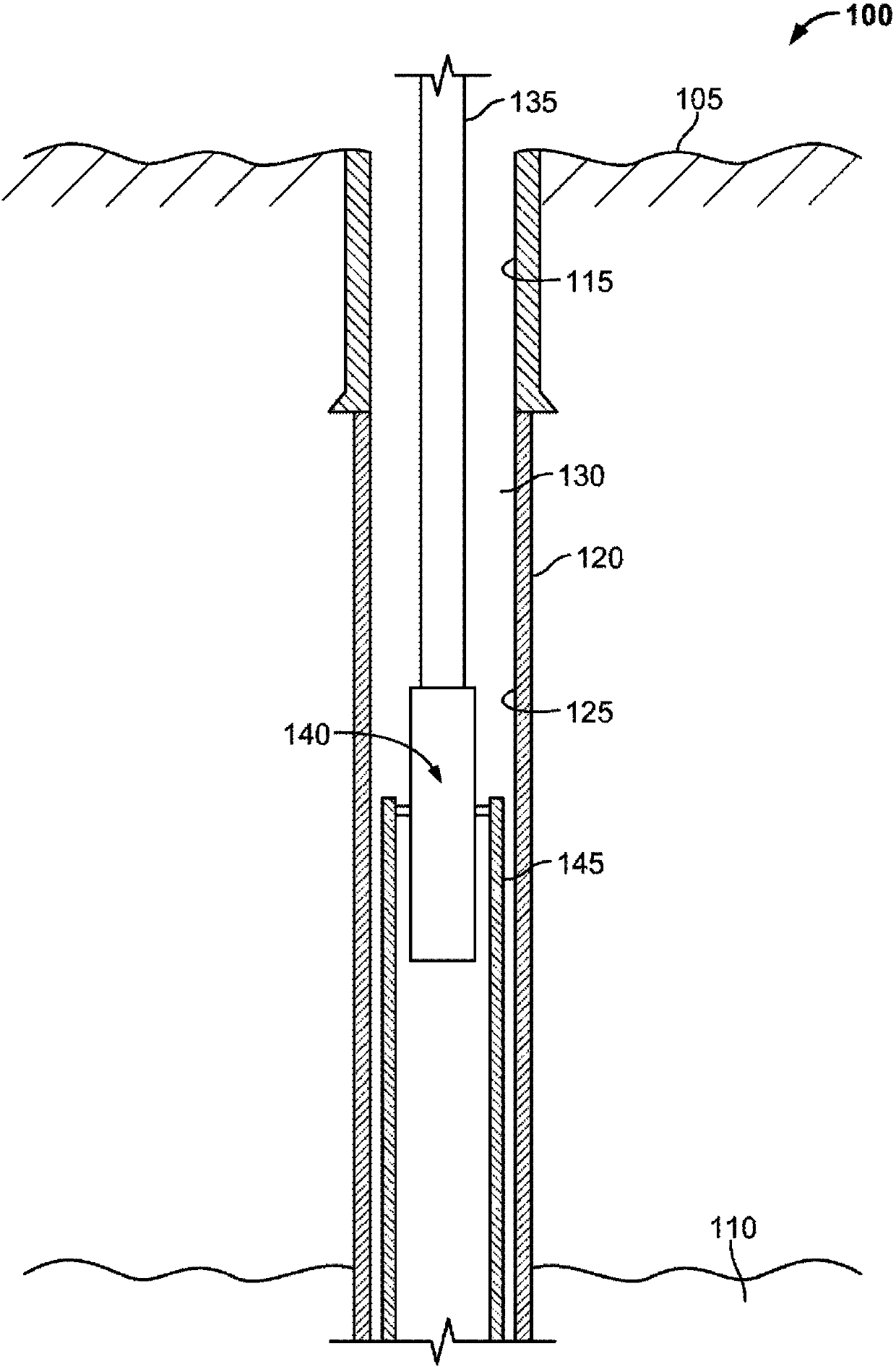
[0031] figure 1 is a schematic diagram of an exemplary wellbore system 100 including a liner top system 140 . Overall, figure 1 A portion of one embodiment of a wellbore system 100 is shown in which a liner top system 140 may be lowered into a wellbore 120 to install the liner adjacent to casing 125 (eg, production or otherwise casing) in accordance with the present invention 145. In some aspects, the liner top system 140 can also centralize the liner 145 prior to installation, and install a sealing member (e.g., a packer, liner top packer, or packing element) on the top of the liner 145. at the top.

[0032] In some aspects, the liner 145 is an alternative to a conventional liner suspension system (e.g., the liner suspension system includes a liner hanger with a slide, a liner top packer, and a tieback or polish hole receiver ) bare casing joints. For example, in cases where the wellbore 120 is deviated or is a horizontal wellbore section, the weight of the liner can be ...


PUM


Abstract

A liner assembly tool includes a base pipe (306) that includes a bore (308) therethrough; a wellbore liner (312) that includes a liner top and is coupled to the base pipe; a pack-off element (328) radially positioned between the base pipe and the wellbore liner to ride on the base pipe; and a wedge (334) positioned to ride on the base pipe and expand the pack-off element to at least partially sealthe liner top to a wellbore wall based on a particular fluid pressure supplied through the bore.

Description

[0001] Cross References to Related Applications [0002] This application claims priority to US Patent Application Serial No. 14 / 736,613, filed June 11, 2015, the entire contents of which are hereby incorporated by reference. technical field [0003] The present invention relates to sealing a portion of a wellbore, and more particularly to sealing a portion of a wellbore with a liner hanger system. Background technique [0004] During the well construction process, expandable liners may be installed to provide zone isolation or to isolate zones experiencing fluid circulation problems. Sometimes there are failures of expandable liners such as failure to expand, which results in the annulus not being isolated or plugged. In this case, the unexpanded (and unconsolidated) liner can present difficulties for further wellbore operations. For example, without a pressure seal at the top of the sealed liner, drilling operations cannot be restarted, especially if a heavily leaking fo...

Claims


Application Information

Patent Timeline
Patent Type & Authority Applications(China)
IPC IPC(8): E21B23/00E21B33/10
CPCE21B23/00E21B33/10E21B43/10E21B33/1285E21B43/103
Inventor 周韶华
Owner SAUDI ARABIAN OIL CO
Why Eureka
Try Eureka