Brake device for a hydraulic motor vehicle brake system

a brake device and hydraulic technology, applied in the direction of brake systems, vehicle sub-unit features, transportation and packaging, etc., can solve the problems of large construction, negative pressure brake force boosters, and large structural space, and achieve the effect of simple and robust design and simplified integration of them into existing systems

Active Publication Date: 2018-11-15
CONTINENTAL TEVES AG & CO OHG
View PDF3 Cites 3 Cited by
  • Summary
  • Abstract
  • Description
  • Claims
  • Application Information

AI Technical Summary

Benefits of technology

[0012]The brake device according to an aspect of the invention is distinguished by its particularly simple and robust design. It can furthermore be constructed in modular fashion, combined with different master brake cylinders, motor-pump units and downstream modulator units, and used on existing fastening interfaces in the vehicle, even as a replacement for negative-pressure brake force boosters. In this way, a wide variety of customer-specific characteristics can be replicated with variations of the brake device according to an aspect of the invention, and the integration thereof into existing systems can be simplified.

Problems solved by technology

With ever-increasing demands on automated, computer-controlled driving and braking, and at the same time an ever-decreasing available structural space, negative-pressure brake force boosters, which are of large construction, reach their technical limits.
Known generic brake devices are normally of complex construction with electrically switchable valve devices for implementing different actuation modes.
To ensure that the brake pedal is driven along in an autonomous actuation situation, it is likewise the case in known brake devices that cumbersome technical solutions are necessary.
Known brake devices with hydraulic booster stages which use heavy and expensive high-pressure accumulators as a pressure source are considered to have particular potential for improvement owing to the increased weight, structural space expenditure and switching effort.

Method used


Image

  • Brake device for a hydraulic motor vehicle brake system
  • Brake device for a hydraulic motor vehicle brake system
  • Brake device for a hydraulic motor vehicle brake system

Examples


Embodiment Construction
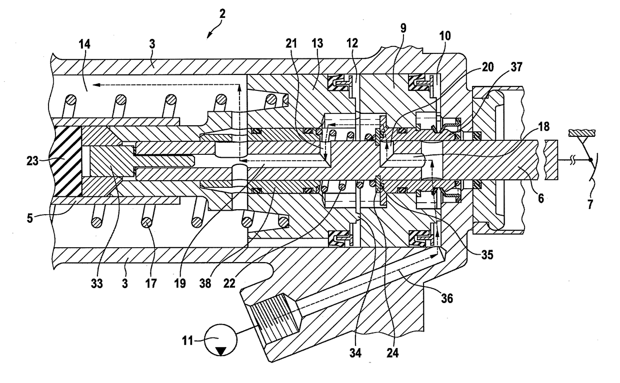
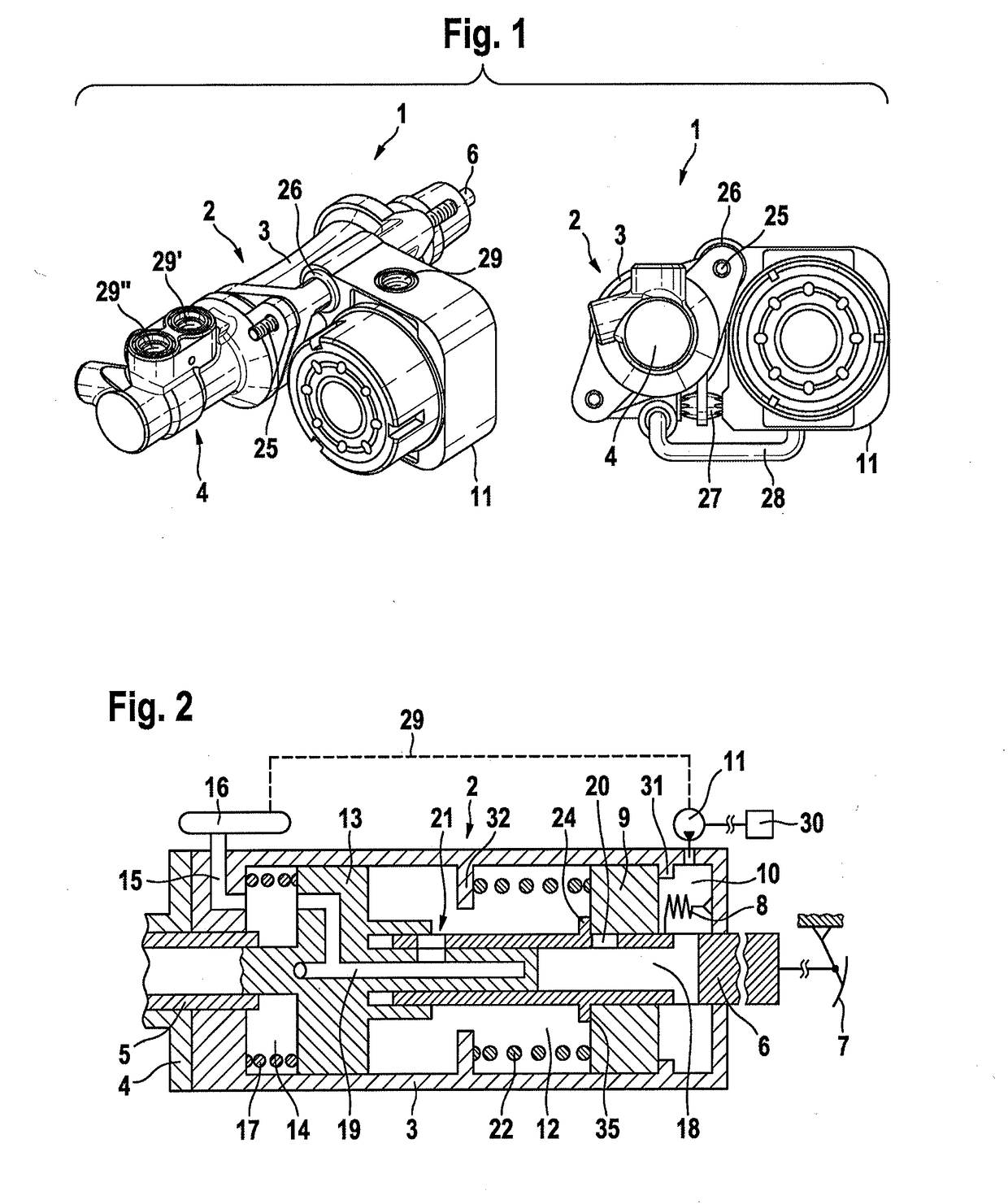
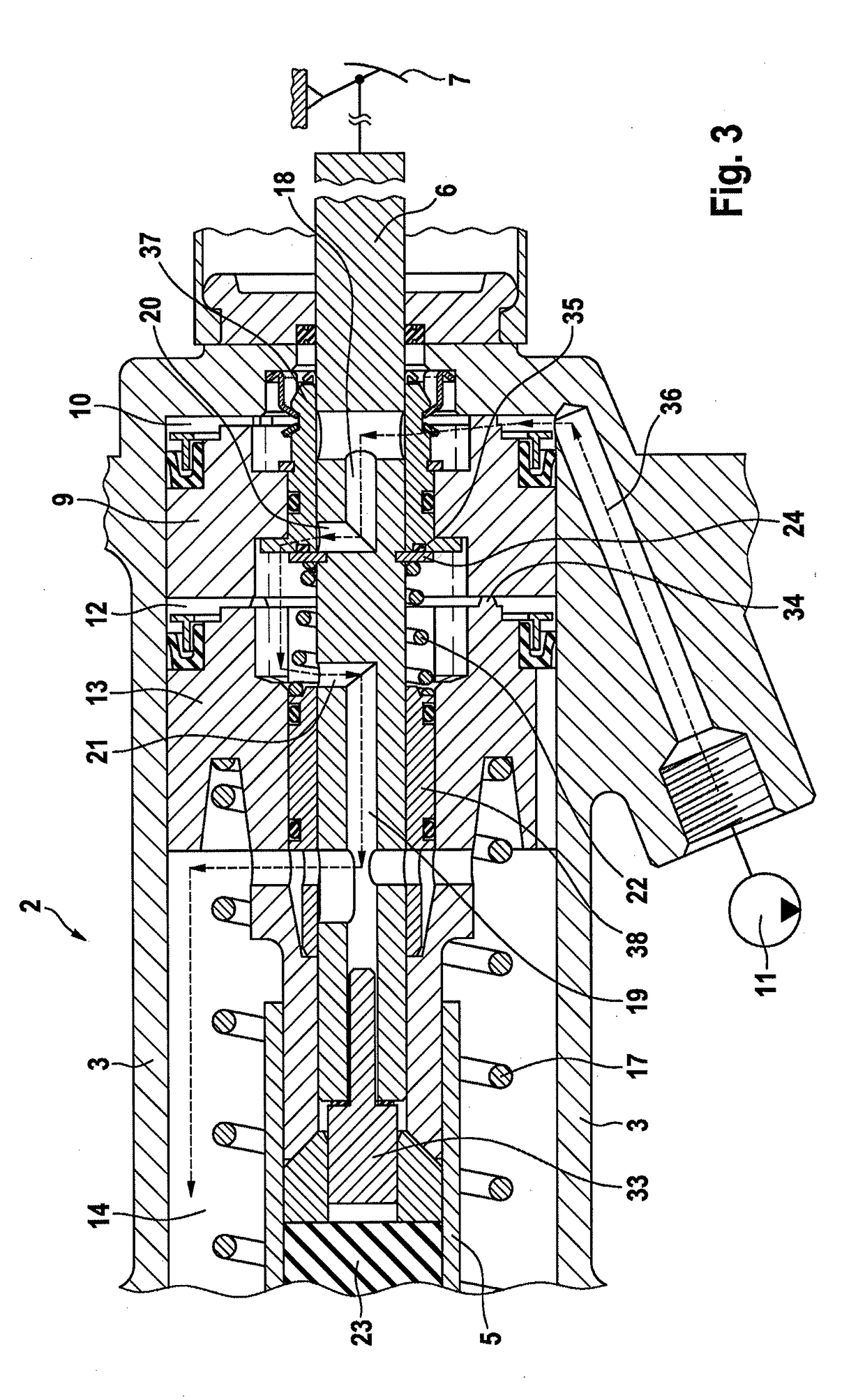
[0020]FIG. 1:

[0021]An embodiment of the brake device 1 according to an aspect of the invention is illustrated in FIG. 1 in external views (three-dimensional and front view). The brake device 1 is of modular construction and comprises substantially a hydraulic booster stage 2 with a booster housing 3, a master brake cylinder 4, and an electrically driven motor-pump unit 11.

[0022]The booster stage 2 is actuated, via an axially displaceable piston rod 6, by a brake pedal 7 (not shown here), possibly with the interposition of further conventional mechanical components (not shown here).

[0023]The electromotively driven motor-pump unit 11 is mounted pivotably at the fastening bolt 25 in an elastic radial damper 26, and is supported and fixed against a fastening point on the booster housing 3 with the interposition of an axial damper 27. In this way, torques of the motor-pump unit 11 are, in terms of vibrations, optimally accommodated and isolated.

[0024]In the embodiment shown, the fastenin...


PUM


Abstract

A brake device having a hydraulic booster stage for a hydraulic motor vehicle brake system is provided, which brake device, within normal boosting operation, can be operated both in an autonomous, driver-independent actuation mode with electronic control and in a manual actuation mode controlled by the driver, and outside normal boosting operation, can be operated in an emergency mode with a non-boosted actuation force generated by the driver alone, in the case of which brake device it is proposed that, within normal boosting operation, each actuation mode is assigned a dedicated piston in a booster housing of the booster stage, which piston is acted on directly with the boosting force and transmits this mechanically to components connected functionally downstream.

Description

CROSS REFERENCE TO RELATED APPLICATIONS[0001]This application is the U.S. National Phase Application of PCT International Application No. PCT / EP2016 / 078115, filed Nov. 18, 2016, which claims priority to German Patent Application No. 10 2015 223 047.3, filed Nov. 23, 2015, the contents of such applications being incorporated by reference herein.FIELD OF THE INVENTION[0002]The invention relates to a brake device for a hydraulic motor vehicle brake system having a hydraulic booster stage.BACKGROUND OF THE INVENTION[0003]With ever-increasing demands on automated, computer-controlled driving and braking, and at the same time an ever-decreasing available structural space, negative-pressure brake force boosters, which are of large construction, reach their technical limits. It is therefore known to use brake devices with electromechanically driven hydraulic booster stages.[0004]Such booster stages must ensure reliable functioning both in an externally actuated or fully autonomous, driver-i...

Claims


Application Information

Patent Timeline
Patent Type & Authority Applications(United States)
IPC IPC(8): B60T13/14
CPCB60T13/143B60T13/686B60T7/042B60T17/22B60Y2400/81
Inventor PETZOLD, FALKMESSNER, ADRIANRUFFER, MANFREDJURGING, MICHAEL
Owner CONTINENTAL TEVES AG & CO OHG
Why Eureka
Try Eureka