Compressed air nailer with safety valve arrangement

a safety valve and compressor technology, applied in the field of compressors, can solve the problems of unnecessary supply of electrical energy, and achieve the effect of promoting a particularly compact design and compact design

Active Publication Date: 2020-10-01
BEA GMBH
View PDF0 Cites 2 Cited by
  • Summary
  • Abstract
  • Description
  • Claims
  • Application Information

AI Technical Summary

Benefits of technology

[0027]In one embodiment, the safety control chamber has an annular space that is delimited by two seals inserted between the outer sleeve and the valve sleeve which are spaced from each other in the axial direction and radial direction. This measure as well promotes a particularly compact design. Another advantage is that the volume of the safety control chamber remains uninfluenced by an actuation of the valve pin.
[0028]In one embodiment, there is a continuously aerated counterpressure chamber, wherein the pressure in the counterpressure chamber exerts a counterforce on the valve sleeve which is directed in the direction opposite the force exerted on the valve sleeve by the pressure in the safety control chamber. Alternatively and / or in addition, a spring can be used to exert a counterforce on the valve sleeve. The use of a continuously aerated counterpressure chamber is particularly advantageous because the force exerted by the pressure in the safety control chamber and the counterforce exerted by the pressure in the counterpressure chamber equally depend on the operating pressure of the compressed air nailer. This leads to a functioning of the safety mechanism that is largely independent of pressure fluctuations.
[0029]In one embodiment, the counterpressure chamber has an annular space that is delimited by two seals adjacent to the valve sleeve which are spaced from each other in the axial direction and radial direction. This also contributes to a particularly compact design. In addition, with this annular counterpressure chamber design, the valve pin can be easily guided to the outside through a middle opening in the counterpressure chamber.

Problems solved by technology

Both the driving as well as the controlling of the compressed air nailer can be entirely pneumatic; a supply with electrical energy is therefore unnecessary.

Method used


Image

  • Compressed air nailer with safety valve arrangement
  • Compressed air nailer with safety valve arrangement
  • Compressed air nailer with safety valve arrangement

Examples


Embodiment Construction

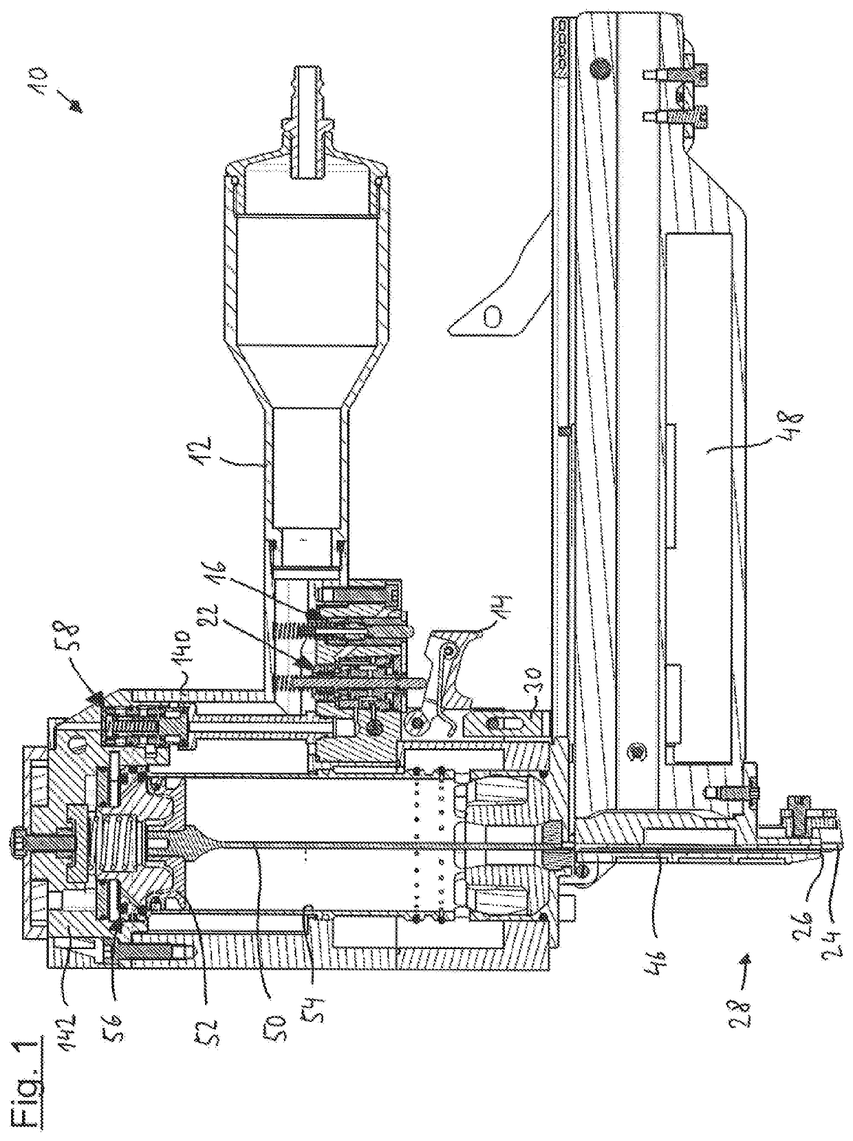
[0038]Initially, a few important elements of the compressed air nailer 10 will be described, some summarily, with reference to FIG. 1. The compressed air nailer 10 has a handle 12 that is attached to a lower housing part 140 which is closed at the top by a housing cap 142.

[0039]The compressed air nailer 10 has a placing sensor 24 that projects downward a few millimeters beyond the mouth 26 of an outlet tool 28. If the compressed air nailer 10 is placed onto a workpiece, the placing sensor 24 is displaced upward against the force of a spring (not shown) until it abuts the mouth 26 flush or projects just slightly above the mouth 26. The placing sensor 24 is mechanically coupled to a force transmission element 30 which also moves upward when the placing sensor 24 moves.

[0040]The outlet tool 28 has a receiver 46, in each case a fastening means being supplied thereto from a magazine 48. From this position inside the receiver 46, the fastening means—for example a nail, a tack or a staple—...


PUM


Abstract

A compressed air nailer comprises a control line configured to trigger a driving process when a valve pin is displaced relative to a valve sleeve into an actuated position. The valve sleeve is configured to move between a triggering position and a locked position. A switching surface is coupled to at least one of a trigger and a placing sensor and configured to actuate the valve pin. An outer sleeve is configured to guide the valve sleeve. The switching surface is positioned at a switching surface position relative to the outer sleeve when both the trigger and the placing sensor are actuated. The switching surface is configured to displace the valve pin into the actuated position when the valve sleeve is positioned in the triggering position. The switching surface does not displace the valve pin into the actuated position when the valve sleeve is positioned in the locked position.

Description

CROSS REFERENCE TO RELATED INVENTION[0001]This application is a national stage application pursuant to 35 U.S.C. § 371 of International Application No. PCT / EP2018 / 076332, filed on Sep. 27, 2018, which claims priority to, and benefit of, European Patent Application No. 17 199 525.1, filed Nov. 1, 2017, the entire contents of which are hereby incorporated by reference.BACKGROUND[0002]The invention relates to a compressed air nailer that has a trigger, a placing sensor and a trigger valve with a valve pin and valve sleeve. When the valve pin is displaced relative to the valve sleeve into an actuated position, a control line is aerated or deaerated in order to trigger a driving process. The valve pin is actuated by a switching surface which is coupled to the trigger and / or to the placing sensor.[0003]If such a compressed air nailer is placed onto a workpiece, the placing sensor is displaced against the force of the spring until an outlet tool lies on, or nearly on, the workpiece. Only w...

Claims


Application Information

Patent Timeline
Patent Type & Authority Applications(United States)
IPC IPC(8): B25C1/00B25C1/04
CPCB25C1/047B25C1/042B25C1/046B25C1/008B25C1/043
Inventor THEBERATH, MARTINJUNG, FLORIANBAUER, JOACHIM
Owner BEA GMBH
Why Eureka
Try Eureka