Disc brake and set of brake pads

A technology of disc brakes and brake linings, which is applied in the types of brakes, components of brakes, brakes in the axial direction, etc., can solve problems such as uneven wear of brake linings, and achieve the effect of weight reduction and uniform loading.

Active Publication Date: 2018-09-28
BENDIKS SPAJSER FAUNDEJSHN BREJK LLK +1
View PDF9 Cites 3 Cited by
  • Summary
  • Abstract
  • Description
  • Claims
  • Application Information

AI Technical Summary

Problems solved by technology

[0006] In the case of disc brakes, especially with only one force introduction element, this design can cause uneven wear of the brake linings

Method used


Image

  • Disc brake and set of brake pads
  • Disc brake and set of brake pads
  • Disc brake and set of brake pads

Examples


Embodiment Construction

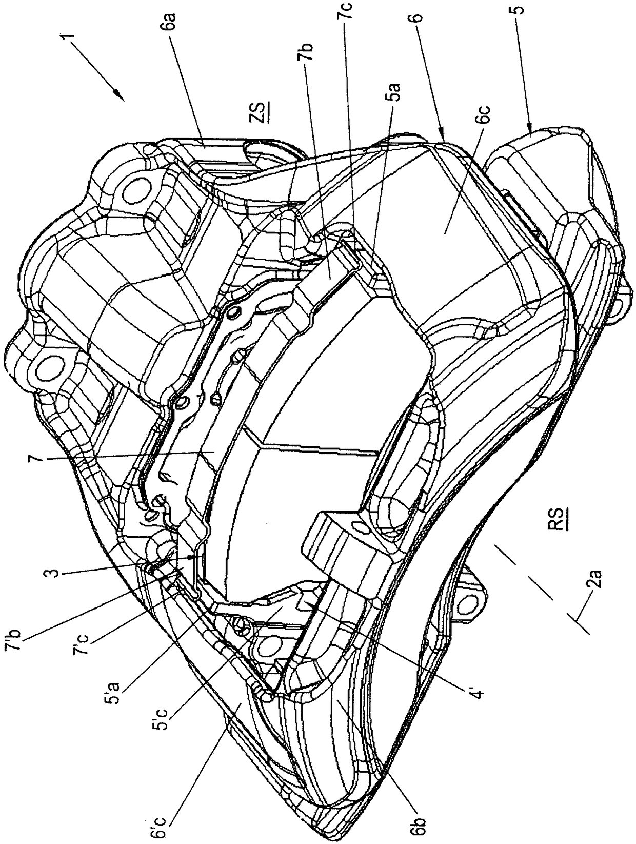
[0052] Such disc brakes are used in particular in commercial vehicles and are often pneumatically actuated. One embodiment of such a disc brake caliper is in the form of a sliding caliper and is used in a constrained construction space, for example in the vicinity of an adjacent wheel rim.

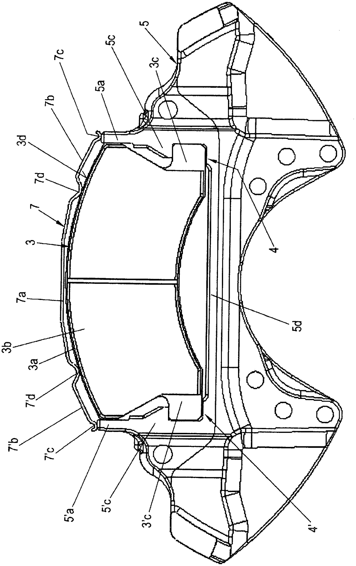
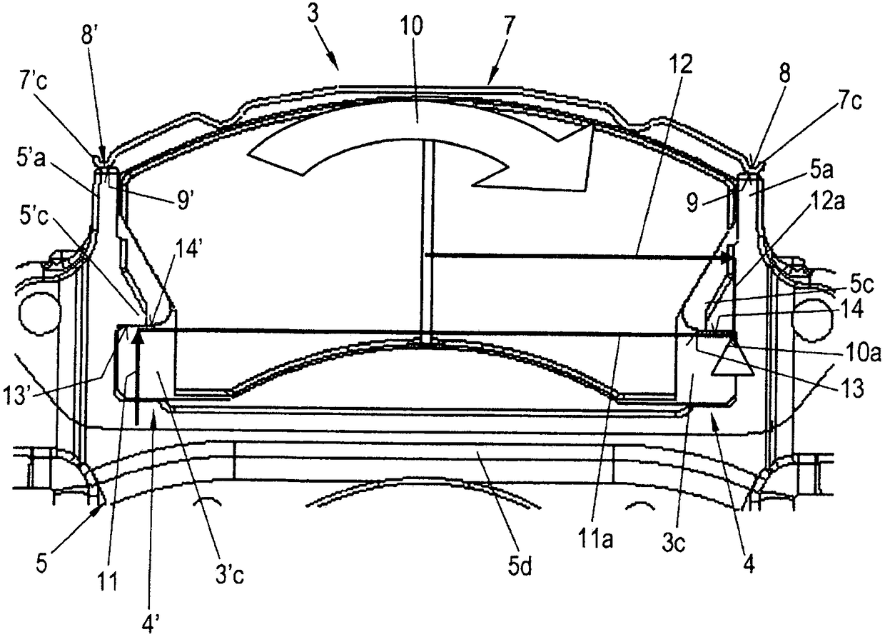
[0053] figure 1 A perspective view of a first embodiment of a disc brake 1 , for example a pneumatic disc brake 1 , according to the invention is shown. Figure 2 to Figure 4 shows according to figure 1 A partial view of a brake carrier 5 of a disc brake 1 according to the invention having a brake lining 3 according to the invention. For more clarity, figure 1 The brake disc 2 is not shown, but it is easily imagined, for example as Figure 9 shown. figure 2 A plan view of the friction lining 3 b of the brake lining 3 in the brake carrier 5 is shown. image 3 The forces 11 , 12 acting on the brake lining 3 are shown.

[0054] Figure 4 An enlarged view of the side of the brake lini...


PUM


Abstract

A disc brake for a vehicle, in particular for a commercial vehicle, is provided. The disc brake includes at least one application-side brake pad and a back-side brake pad held in a form-fitting mannerin a brake carrier. At least the application-side brake pad is provided with at least one pad-retaining spring which is supported at least on one brake carrier horn of the brake carrier and exerts aradially outwardly acting tensile force on the brake pad.

Description

[0001] Cross References to Related Applications [0002] This application claims the benefit of US Application No. 14 / 939,748, filed November 12, 2015, the contents of which are hereby incorporated by reference in their entirety. technical field [0003] The present invention relates to a disc brake and a brake lining set for a disc brake, and more particularly to a brake lining retaining arrangement. Background technique [0004] Such disc brakes are used in particular in commercial vehicles and are often provided with pneumatic actuation. One embodiment of such a disc brake caliper is in the form of a sliding caliper and is used in compact construction spaces, for example in the vicinity of adjacent wheel rims. [0005] The sliding brake caliper is usually connected to the supporting brake carrier via two bearing columns designed as fixed bearings and movable bearings. The brake pads of the disc brake are displaceably guided in the brake carrier and are typically held in...

Claims


Application Information

Patent Timeline
Patent Type & Authority Applications(China)
IPC IPC(8): F16D65/097F16D55/225F16D55/226F16D55/2265F16D55/227F16D65/092
CPCF16D55/226F16D65/0976F16D65/0978F16D2065/026F16D2250/0084
Inventor M·舍瑙尔W·帕勒M·巴特尔T·费施尔J·鲍姆加特纳A·佩特施克R·L·兰茨R·S·泰凯斯基M·博希曼
Owner BENDIKS SPAJSER FAUNDEJSHN BREJK LLK
Why Eureka
Try Eureka