
Apparatus for pressure sensing

a technology of pressure sensing and apparatus, which is applied in the direction of apparatus for force/torque/work measurement, force measurement by measuring optical property variation, instruments, etc., can solve the problems of difficult diagnosis, high cost of devices, and often uncomfortable for patients with diagnostic tools, so as to facilitate compact enclosure design, and reduce the temperature related change

Active Publication Date: 2013-08-06
ARKWRIGHT TECH PTY LTD
View PDF18 Cites 5 Cited by
  • Summary
  • Abstract
  • Description
  • Claims
  • Application Information

AI Technical Summary

Benefits of technology

The patent describes an apparatus for measuring pressure in the oesophagus of a person. It includes several enclosures with rigid walls and moveable walls that have Bragg gratings. Each enclosure is attached to the light guide to prevent strain on the sensing regions from external strain on the light guide. The apparatus also has an external catheter for positioning in the human body. The moveable walls have a dual function of reducing temperature-related changes in the optical response of the Bragg gratings and responding to external pressure changes. This design allows for a smaller distance between the sensing regions. Overall, the apparatus provides accurate and reliable pressure measurement in the human body.

Problems solved by technology

It is difficult to diagnose this disease and diagnostic tools are often very uncomfortable for the patient.
Such devices typically are expensive and require a relatively large number of electrical wires to be contained in a catheter which consequently is of relatively large thickness.
The device is inserted through the nose of the patient and its relatively large diameter results in discomfort for the patient.

Method used


Image

  • Apparatus for pressure sensing
  • Apparatus for pressure sensing
  • Apparatus for pressure sensing

Examples


Embodiment Construction

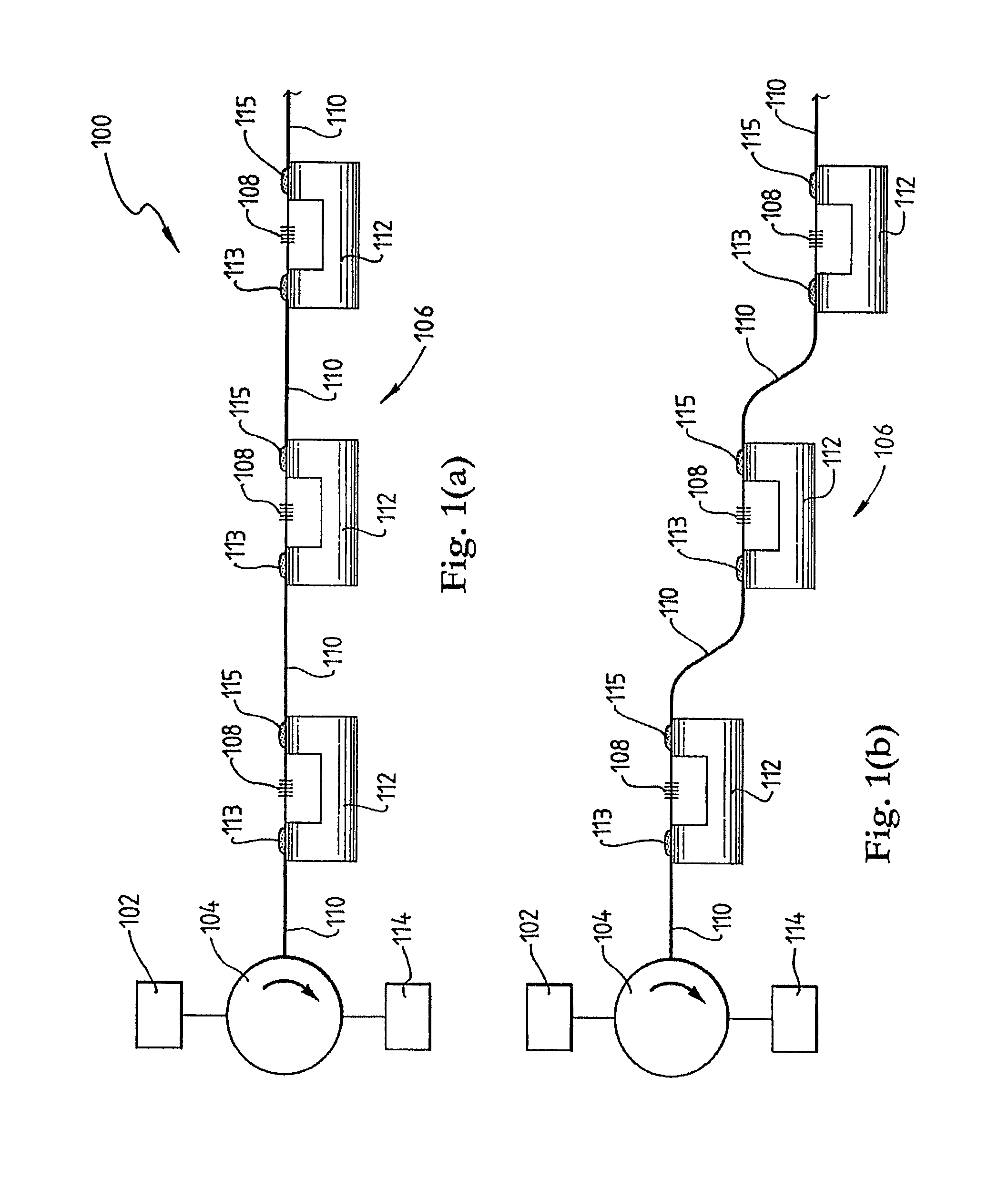
[0042]Referring initially to FIG. 1 (a), a system for distributed pressure measurement according to a specific embodiment of the present invention is now described. The system 100 comprises a light source 102 which in this embodiment is a broadband light source commonly referred to as a “white” light source even though the light that is emitted by the light source 102 may have any wavelength range.

[0043]The light is directed via optical circulator 104 to an apparatus for distributed pressure sensing 106. In a variation of this embodiment the circulator 104 may be replaced by an optical coupler, an optical splitter or an optical beam splitter.

[0044]The apparatus 106 may comprise a catheter (not shown) for insertion into the human body. Further, the apparatus 106 typically comprises an X-ray opaque material, such as a metallic material, for locating the apparatus 106 in the human body.

[0045]The apparatus 106 comprises a series of Bragg gratings 108 which are formed in an optical fibre...


PUM


Abstract

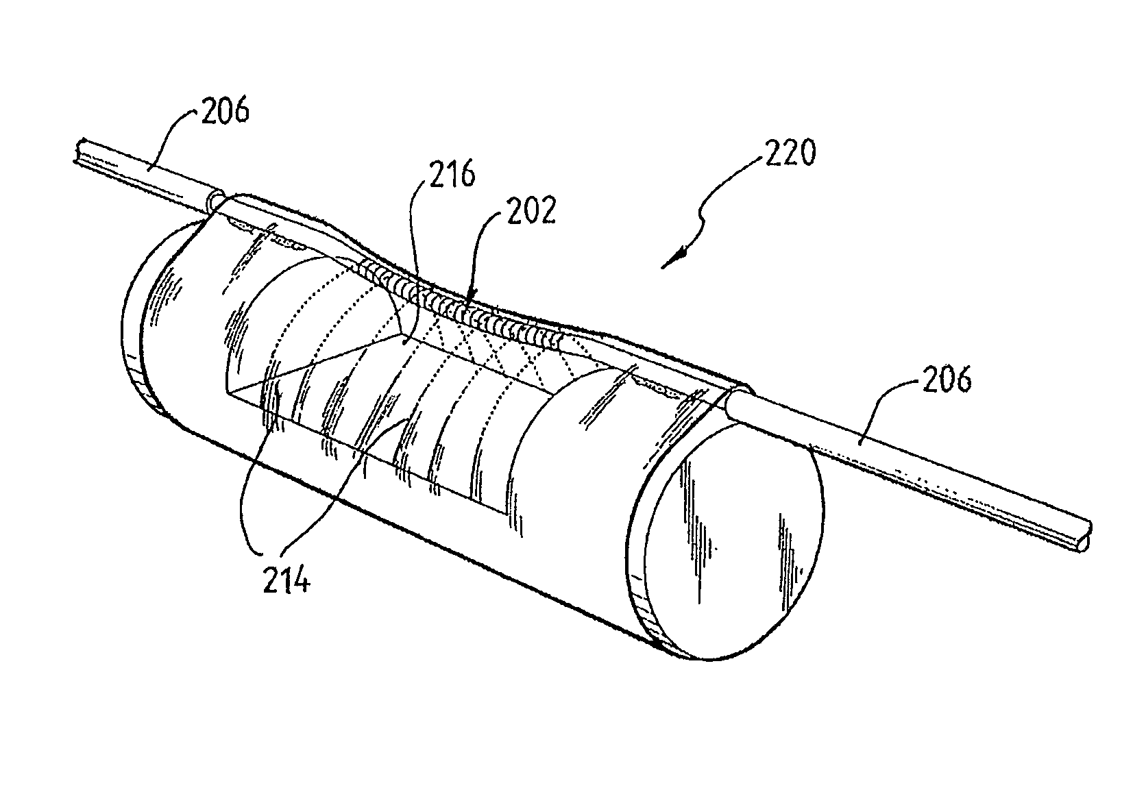
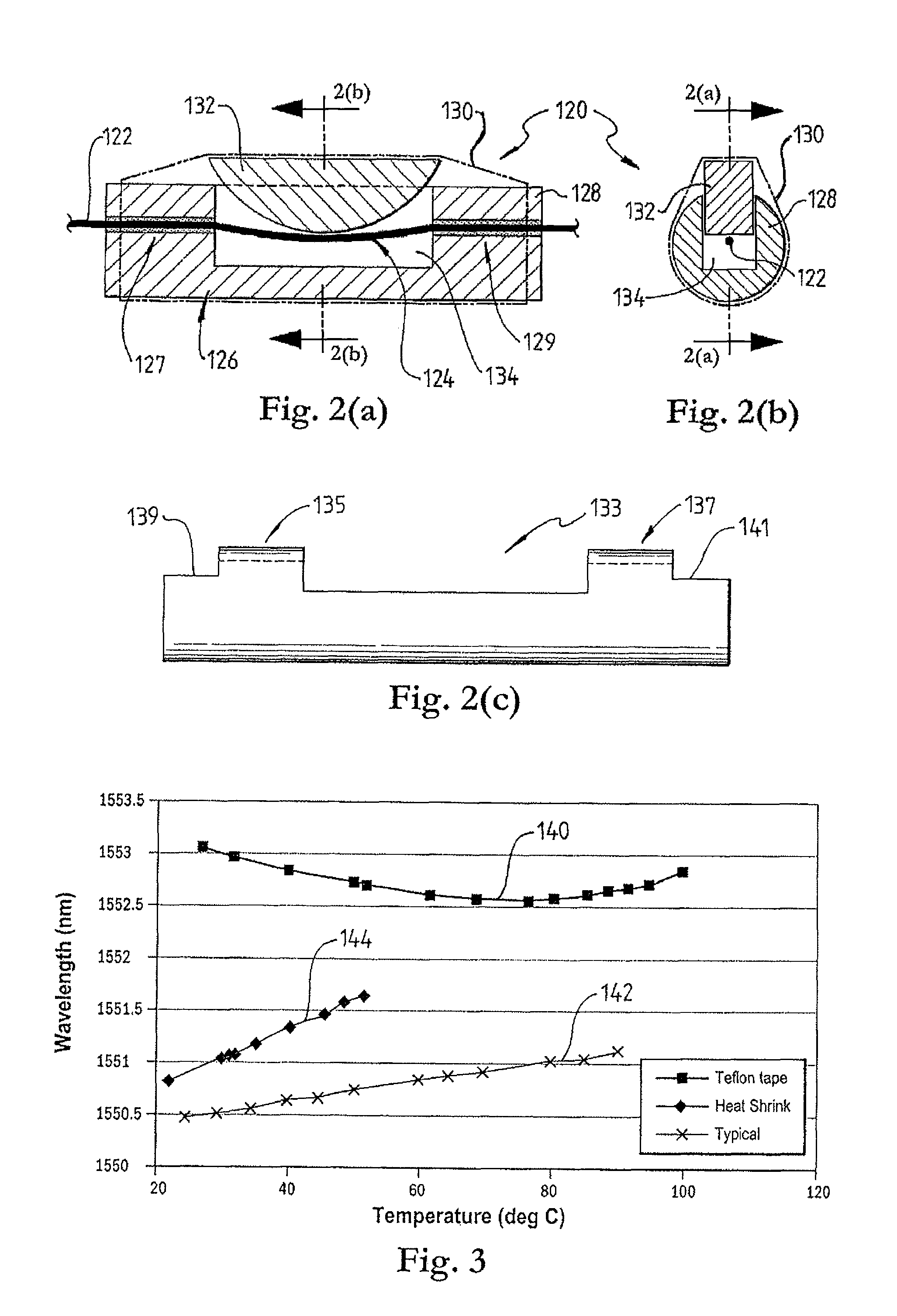
The present invention provides an apparatus for distributed pressure sensing. The apparatus comprises a series of Bragg gratings, a light guide incorporating the series of Bragg gratings and a plurality of moveable wall portions. The moveable wall portions are coupled to respective Bragg gratings so that the movement of one of the moveable wall portion causes a force on the respective Bragg grating resulting in a change in strain of the respective Bragg grating. The apparatus also comprises at least one rigid member that is attached at attachment regions between which a sensing region of at least one Bragg grating is defined. The rigid member is arranged so that a strain in the sensing region is not directly influenced by a change in strain of the light guide outside the sensing region.

Description

FIELD OF THE INVENTION[0001]The present invention broadly relates to an apparatus for pressure sensing.BACKGROUND OF THE INVENTION[0002]The human body has many regions in which pressure differences cause matter to move. For example, the human heart pumps blood through the body. Muscles around the alimentary, canal apply a pressure to the channel which moves food from the mouth into the stomach. Further, a pressure increase in a portion of the body may be caused by a chemical reaction such as the development of a gas in an enclosed body cavity.[0003]Monitoring pressures in the human body can provide important information about the function of the human body and can be used to detect disorders and diseases or can be used to control a recovery from a disease.[0004]For example, dysphagia, which is a disorder that causes difficulty in swallowing, typically affects infants and elderly people and is especially prevalent in post-stroke patients. It is difficult to diagnose this disease and ...

Claims


Application Information

Patent Timeline
Patent Type & Authority Patents(United States)
IPC IPC(8): G02B6/00A61B5/11
CPCG01L1/246G01L1/247G01D5/35316G01L11/025G02B6/022
Inventor ARKWRIGHT, JOHN WILLIAMDOE, SIMON NICHOLASTYAGI, VINAY KUMARPRESTON, EDWARD WILLIAM
Owner ARKWRIGHT TECH PTY LTD
Learn More