Optical Device

a technology of optical devices and bragg gratings, which is applied in the direction of catheters, instruments, angiography, etc., can solve the problems of only providing reliable information about the pressure of optical devices, unable or convenient detection of temperature changes, and affecting the accuracy of optical devices, so as to reduce reduce the force and reduce the temperature-related change in the strain of the bragg grating

Inactive Publication Date: 2008-11-13
COMMONWEALTH SCI & IND RES ORG
View PDF11 Cites 27 Cited by
  • Summary
  • Abstract
  • Description
  • Claims
  • Application Information

AI Technical Summary

Benefits of technology

[0012]In this embodiment the dual function of the moveable wall portion, namely reducing a temperature related change in the optical period of the Bragg grating and causing a force on the Bragg grating in response to an external pressure change, facilitates a compact design of the optical device.
[0016]The moveable wall portion typically is a diaphragm and, at ambient temperature and pressure, typically is positioned so that the diaphragm applies the force on the Bragg grating in a manner such that the distortion of the Bragg grating into the enclosed space increases. Consequently, a temperature related change in material properties of the diaphragm, such as a property related to the Young's modulus, thermal expansion or other such properties, typically reduces the force on the Bragg grating and thereby reduces a temperature related change in strain of the Bragg grating between the attachment regions caused by a thermal expansion of the Bragg grating.
[0017]Further, a temperature increase will typically result in an increase of a pressure in the enclosed space which typically will also reduce the force applied by the diaphragm on the Bragg grating and thereby reduces a temperature related change in strain of the Bragg grating between the attachment regions.
[0018]As the temperature related change in strain of the or each Bragg grating is reduced, the pressure measurement is largely independent from changes in temperature, at least over a predetermined temperature range, which has significant practical advantages.

Problems solved by technology

However, temperature changes also effect a change in the interference conditions of such Bragg gratings.
Consequently such optical devices can only provide reliable information about the pressure if the temperature is known.
For many applications the detection of temperature changes may not be possible or convenient.

Method used


Image

  • Optical Device
  • Optical Device
  • Optical Device

Examples


Embodiment Construction

[0055]FIGS. 1, 2 and 3-7 show embodiments of the optical device or sensing system in which the optical device is an apparatus for pressure sensing. It is to be appreciated, however that the present invention has broader applications and the optical device may not necessarily be a pressure sensing apparatus.

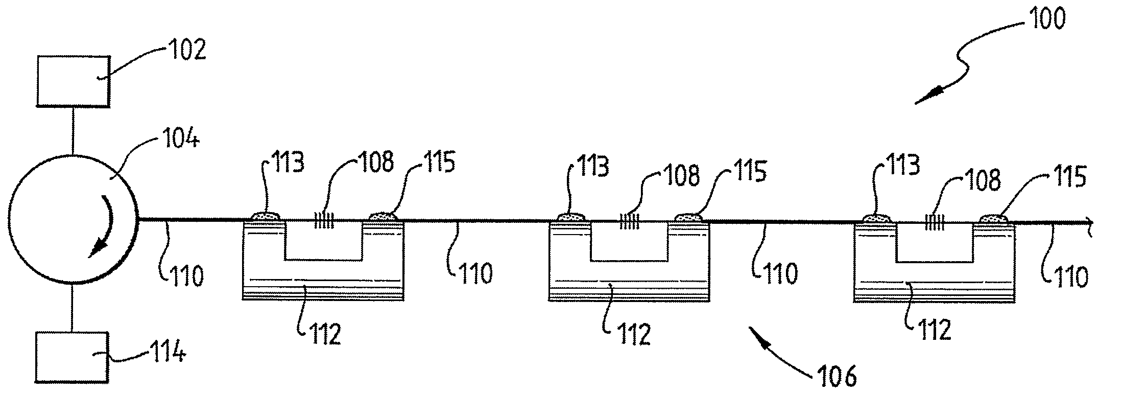
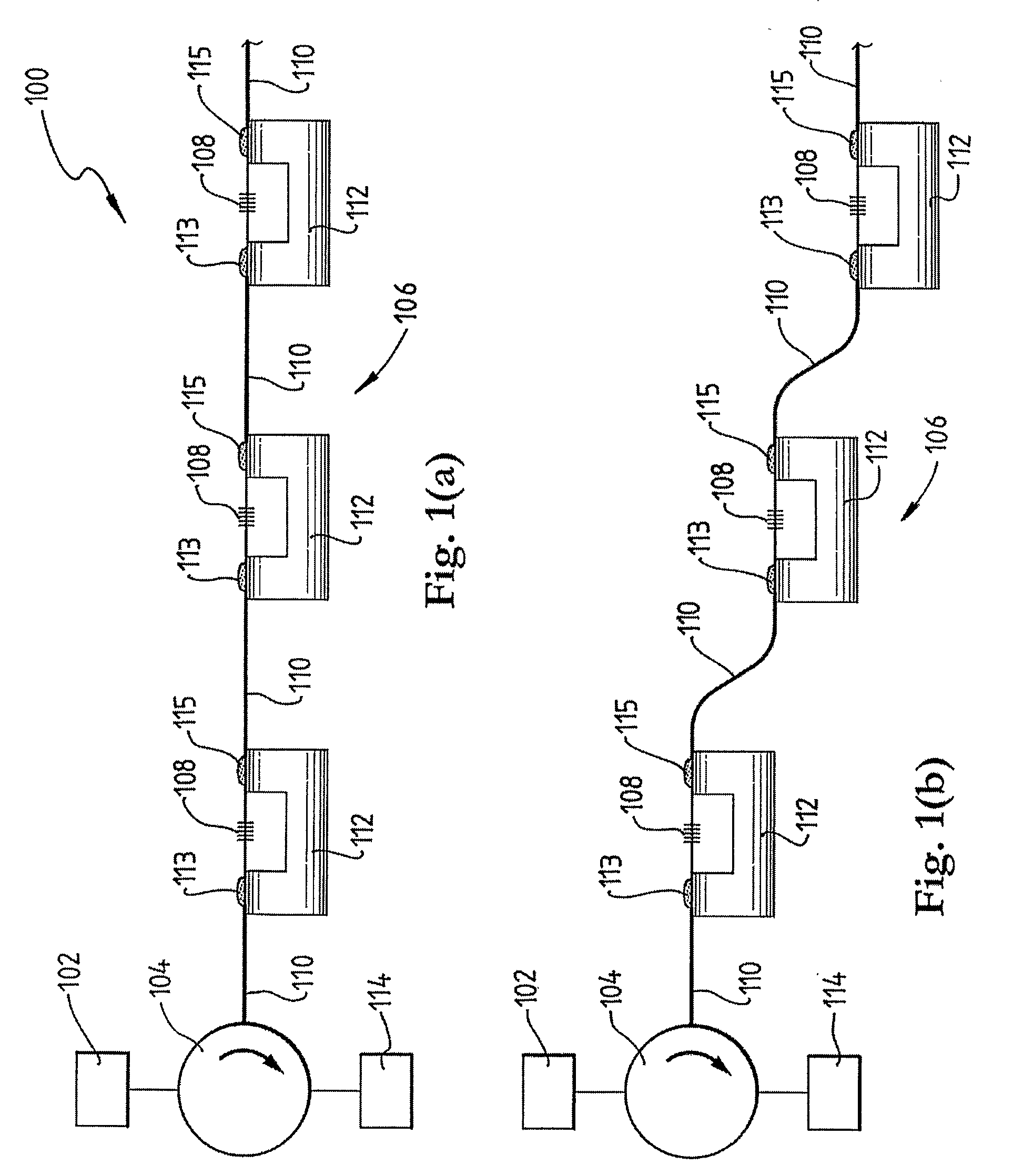
[0056]Referring initially to FIG. 1 (a), a system for pressure sensing according to a specific embodiment of the present invention is now described. The system 100 comprises a light source 102 which in this embodiment is a broadband light source commonly referred to as a “white” light source even though the light that is emitted by the light source 102 may have any wavelength range.

[0057]The light is directed via optical circulator 104 to an apparatus for pressure sensing 106. In a variation of this embodiment the circulator 104 may be replaced by an optical coupler, an optical splitter or an optical beam splitter.

[0058]The apparatus 106 may comprise a catheter (not shown) for ins...


PUM

PropertyMeasurementUnit
temperatureaaaaaaaaaa
thicknessaaaaaaaaaa

Abstract

The present invention provides an optical device which comprises a light guide incorporating a Bragg grating. The apparatus also comprises a moveable wall portion which is coupled to the Bragg grating so that a movement of the wall portion causes a force that effects a change in strain of the Bragg grating and thereby effects a change in an optical period of the Bragg grating. A temperature related change in the optical period of the Bragg grating is reduced by a temperature related change in the force on the Bragg grating by the moveable wall portion.

Description

FIELD OF THE INVENTION[0001]The present invention broadly relates to an optical device and relates particularly, though not exclusively, to an apparatus for pressure sensing.BACKGROUND OF THE INVENTION[0002]Pressure measurements are conducted in a variety of different media and for a variety of different purposes. For example, pressure is measured in open air, under water and in devices or machines. Mechanical or electronic devices typically are used for such pressure measurements.[0003]Recently optical pressure measurement devices became popular in which an external pressure change effects a change in light interference conditions which can be detected. Such an optical device may comprise a fibre Bragg grating which has an optical response that depends on a strain of the Bragg grating. Specifically, if the strain is increased, a wavelength of a reflected light beam will shift to longer wavelengths.[0004]Such optical devices have the advantage that they can be relatively small and m...

Claims


Application Information

Patent Timeline
Patent Type & Authority Applications(United States)
IPC IPC(8): A61B6/00G02B6/34C03B37/07
CPCA61B5/0215G01D5/35303G01L1/246G02B6/2932G02B6/29322G02B7/008G01D5/35316G01D5/35354
Inventor ARKWRIGHT, JOHN WILLIAMDOE, SIMON NICHOLASTYAGI, VINAY KUMARPRESTON, EDWARD WILLIAM
Owner COMMONWEALTH SCI & IND RES ORG
Why Eureka
Try Eureka