DNA amplification device

a dna amplification and amplification technology, applied in the field of dna amplification devices, can solve the problems of reducing reducing process efficiency, and reducing process efficiency. the effect of reducing the duration and improving the process efficiency and power saving properties

Inactive Publication Date: 2006-07-27
THERMOGEN
View PDF10 Cites 28 Cited by
  • Summary
  • Abstract
  • Description
  • Claims
  • Application Information

AI Technical Summary

Benefits of technology

[0012] The objective of the present invention is to provide a DNA amplification device that enables the prompt temperature-rising and temperature-falling controls, and that realizes the flexible and accurate temperature control, where the reduction of the duration in one process enables the improvement of the process efficiency and the power saving properties.
[0013] Another objective of the present invention is to provide a DNA amplification device where excellent thermal responsiveness is secured and the temperature variation on the heat radiation side of the thermo-modules is reduced, and where the reduction of the stress added to the peltiert elements comprising the thermo-module prevents thermal stress fracture at the thermo-module(s), enhancing durability (life expectancy).
[0014] Another objective of the present invention is to provide a DNA amplification device where the high quality of a processing block that has cells which can contain a reaction solution including a DNA sample, can be easily realized, and where the accuracy and stability of physical effects can be secured.
[0015] Another objective of the present invention is to provide a DNA amplification device where the uniform heat distribution enables the reducing variation of temperatures between each cell, and where the variance or shift of positions upon assembly or operation of each cell can be reduced.

Problems solved by technology

However, in the case of using a processing block provided with this cell group for the DNA amplification device, there are problems that the following nonconformities may occur:
However, this DNA amplification device cannot sufficiently respond to this required performance.
alized. Without prompt temperature-rising & temperature-falling controls, there is not only no realization of flexible and accurate temperature control, but also in the longer duration in one process, it will lead the reduction of process efficiency and the reduction of power saving pro
However, there is a limit to enlargement of the volume of the heat sink 53.
In addition, in the case that the multiple thermo-modules 3 are scattered and arranged, the temperature greatly varies between each thermo-module 3, so even DND amplification to all cells cannot be performed.

Method used


Image

  • DNA amplification device
  • DNA amplification device
  • DNA amplification device

Examples


Embodiment Construction

[0037] Preferred embodiments relating to the present invention are described hereafter, with reference to the drawings. The present invention is not limited to the attached drawings which are provided for easily understanding the present invention. Further, detailed descriptions of the well-known portions are omitted in order to avoid ambiguity.

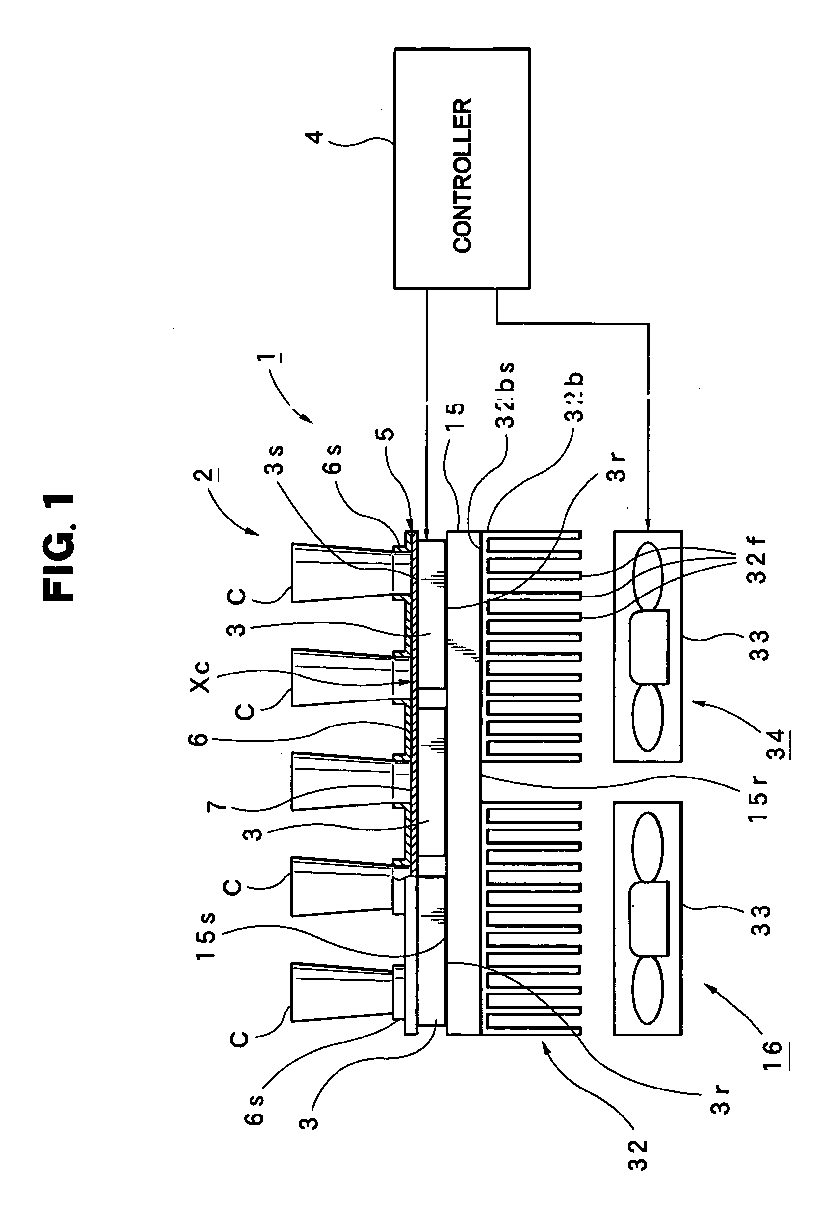
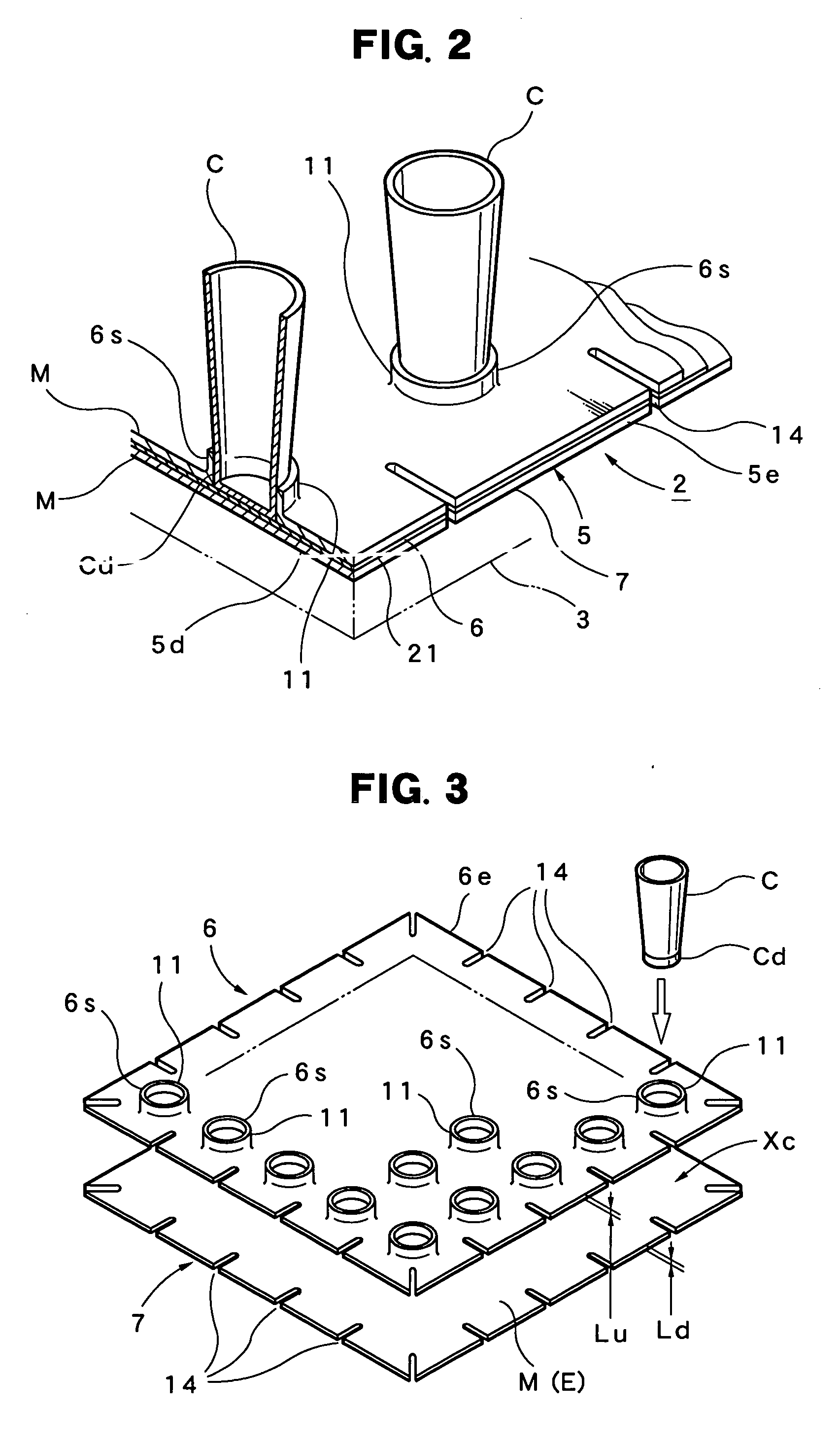
[0038] First, the construction of a DNA amplification device 1 relating to the present invention is described hereafter with reference to FIG. 1 through FIG. 3.

[0039] In FIG. 1, the symbol 3 . . . indicates one, two or more thermo-modules. Each thermo-module 3 . . . is the basically the same as the above-mentioned thermo-module 3 shown in FIG. 15. In other words, the thermo-module 3 is constructed with a structure in which multiple peltiert elements d . . . are connected [with each other] and are regarded as the series aggregate P, and this series aggregate P is interposed by a pair of the substrates 51&52. The multiple electrodes e . . . a...


PUM

PropertyMeasurementUnit
thicknessaaaaaaaaaa
thicknessaaaaaaaaaa
temperatureaaaaaaaaaa

Abstract

A processing block 2 is composed of a base 5, where an upper substrate 6 formed with a metal material M and a lower substrate 7 formed with the metal material M or a ceramic material E are adhered, and cells C . . . supported by this base 5; and the cells C . . . are secured to the upper substrate 6 and / or the lower substrate 7 at least via cell positioners 6s . . . established in the upper substrate 6 for positioning the cells C . . . , respectively. At the same time, at least the thickness Ld of regions Xc . . . situated under the cells C . . . in the lower substrate 7 is selected to be 1.0 [mm] or thinner, and, a thermo-module(s) comes into contact with the lower surface of the base 5.

Description

BACKGROUND OF THE INVENTION [0001] 1. Field of the Invention [0002] The present invention relates to a DNA amplification device suitable for use when amplifying DNA (deoxyribonucleic acid). [0003] 2. Description of the Relevant Art [0004] In general, the PCR method (polymerase chain reaction method) is known as a method for DNA amplification. The PCR method is a method where primers, an enzyme(s) and deoxyribonucleoside triphosphate, reacted with a DNA sample, are added to the DNA sample, whereupon the reaction solution is heated (or cooled down) by a heat cycle changed according to a pre-determined temperature pattern, and concurrently, where the sequential repetition of the heat cycle results in the amplification of the DNA. [0005] Another DNA amplification device for realizing the PCR method is also known, for example, in the publication of Japanese Laid-Open Patent Application No. 2003-174863, which discloses a DNA amplification device equipped with a heating & cooling means est...

Claims


Application Information

Patent Timeline
Patent Type & Authority Applications(United States)
IPC IPC(8): C12Q1/68C12M1/34
CPCB01L3/5082B01L3/50851B01L3/50855B01L7/52B01L2200/025B01L2300/0829B01L2300/1822B01L2300/1844
Inventor KUDOH, SEIICHIKOBAYASHI, RYOJI
Owner THERMOGEN
Why Eureka
Try Eureka