Fluid flow modification apparatus

a technology of flow modification and flow field, which is applied in the direction of flow mixers, air braking surfaces, mixers, etc., can solve the problems of difficult control through artefacts, difficult to achieve control through artefacts, and extremely limited control range of flow field, etc., to achieve the effect of mixing noise control, and the applicability of such grids to applications such as mixing and noise control

Inactive Publication Date: 2010-09-09
IMPERIAL INNOVATIONS LTD
View PDF7 Cites 18 Cited by
  • Summary
  • Abstract
  • Description
  • Claims
  • Application Information

AI Technical Summary

Benefits of technology

[0012]As will be expected from the foregoing, since the first surface portion is a surface against which the fluid flows, the first surface portion effectively presents an obstruction to the oncoming fluid, causing the fluid to pass around the turbulence-creating elements. The second surface portion, however, is a surface along which the fluid flows, and therefore presents resistance to the oncoming flow (in the form of friction) as it passes around the elements, leading to development of a shear layer along the second surface portion. The characteristics of the shear layer that is created thereby are dependent on the width of the second surface portion, and since the properties of the shear layer have a significant bearing on the flow field downstream of the fluid flow modification apparatus, the turbulence created by the fluid flow modification apparatus can further be controlled by varying the width of the second surface portion between respective types of elements.

Problems solved by technology

However, as has been realised in the course of many and diverse research projects, flow field behaviour is extremely complex and thus difficult to control by means of artefacts placed within a flow field.
Thus the range of control that is achievable with, and applicability of, such grids to applications such as mixing and noise control, is extremely limited.

Method used


Image

  • Fluid flow modification apparatus
  • Fluid flow modification apparatus
  • Fluid flow modification apparatus

Examples


first embodiment

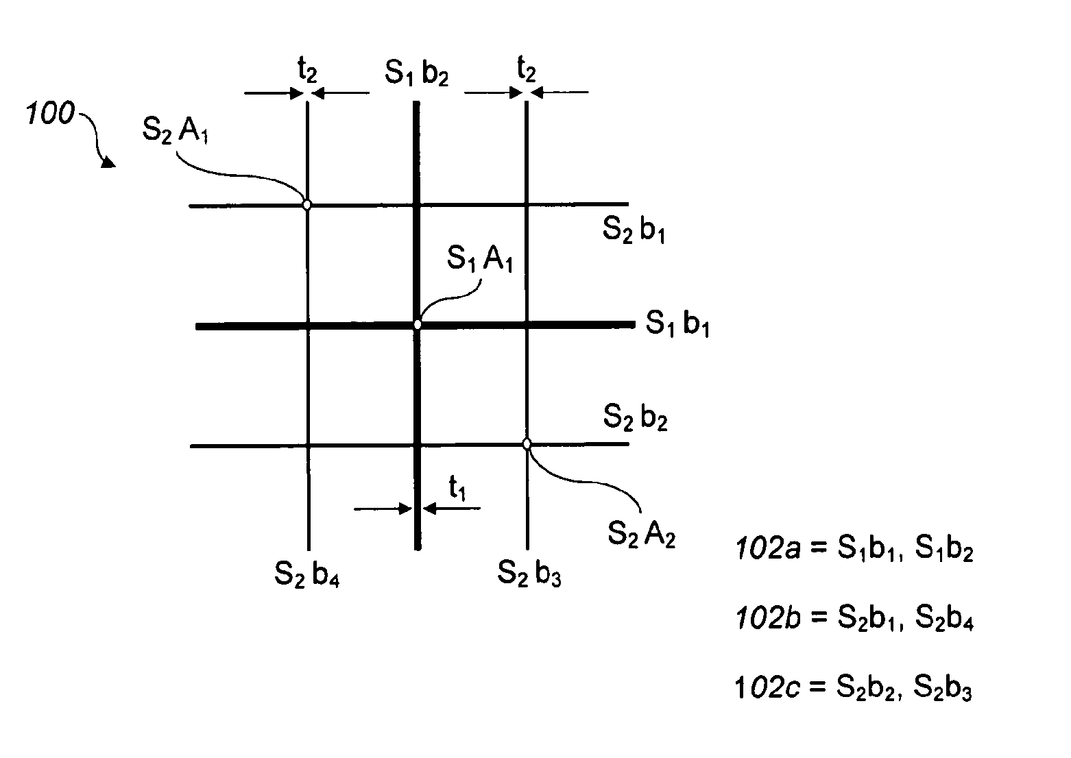
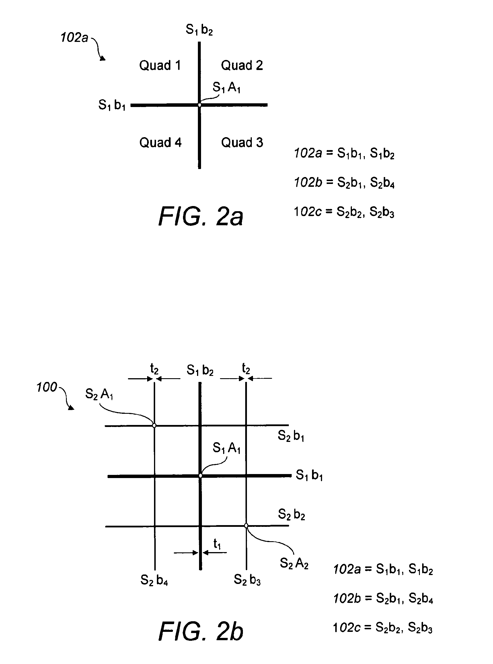
[0068]Turning now to FIGS. 2a and 2b, the fluid modification apparatus 100, hereinafter referred to as a grid, will be described. The grid 100 comprises a plurality of grid elements that are arranged symmetrically with respect to the axis of the test section 101b; the grid elements are selected so as to generate turbulence within fluid flow therethrough and in this embodiment the grid elements are embodied as generally elongate members, substantially uniform along their length, and arranged so as to form a cross-like structure 102a shown in FIG. 2a.

[0069]In this particular example the grid 100 comprises three structures: the first structure 102a is composed of elongate members S1b1 and S1b2; the second structure 102b is composed of elongate members S2b1 and S2b4; and the third structure 102c is composed of elongate members S2b2 and S2b3. For each respective structure the elongate members are interconnected via an attachment point, indicated in FIG. 2a for the first structure 102a b...

second embodiment

[0081]The number of structures making up a given set is constrained by a symmetry condition, which specifies that, with the exception of structures in the last set, each unconnected end of an elongate member in a given set is required to abut a structure in the next set. Accordingly, grid elements according to this second embodiment are arranged in a fractal configuration, since the grid 200 comprises a geometric pattern that is repeated at various scales and can be subdivided into parts, each of which is a smaller copy of the grid as a whole.

[0082]As can be seen from FIG. 5b, the elongate members S1b1, S1b2, S1b3 of the first structure 202a have a thickness different to that of the members of the second-fifth structures 202b . . . 202e, and the thickness of these second-fifth structures 202b . . . 202e is identical. Accordingly, for an example in which the grid 200 comprises two sets S1, S2 of structures, respective sets differ from one another by virtue of the thickness of the mem...

third embodiment

[0088]In a first arrangement of this third embodiment, shown in FIG. 7a, the elongate members of a given structure have the same thickness as that of members of any other structure, since a grid structure comprising grid elements, or elongate members, joined in an end-to-end configuration is itself novel. In an alternative arrangement, and as can be seen from FIG. 7c, the elongate members of the first structure 302a can have a thickness different to that of the members of the second-fifth structures 302b . . . 302e, and the thickness of these second-fifth structures 302b . . . 302e is identical. From a review of FIGS. 7a and 7c it will be noted that in either arrangement, each of the structures 302b-302e of the second set S2 abut two of the elongate members of the structure 302a of the first set S1 (for example, members S2b3 and S2b4 of structure 302b abut elongate members S1b2 and S1b2 respectively of the first structure 302a). As a result each elongate member of a structure in a g...


PUM


Abstract

Embodiments of the invention relate to apparatus for modifying the properties of a flow field and to a method of selecting an apparatus to achieve a desired flow field. The invention finds particular application in the control of the mixing of fluids, heat transfer within and between fluids, acoustic noise, oscillations in fluids, microchip cooling, structural vibrations and chemical reactions. Embodiments of the invention comprise a fractal fluid flow modification structure comprising: a plurality of turbulence-creating elements; and a support for holding the turbulence-creating elements in the fluid so as to allow movement of the fluid relative to the turbulence-creating elements, wherein said turbulence-creating elements include at least two different types of element, including a first type of element and a second type of element, and wherein the turbulence-creating elements are arranged in a fractal structure, the first type of element being arranged at a first level in said fractal structure and the second type of element being arranged at a second level in said fractal structure. Since the fluid flow modification structure comprises a plurality of levels of fractal structures, the surface area of the first type of element differs from that of the second type of element: varying the respective surface areas between fractal levels provides a convenient mechanism for controlling turbulence levels in the fluid.

Description

FIELD OF THE INVENTION[0001]The present invention relates to apparatus for modifying the properties of a flow field and to a method of selecting an apparatus to achieve a desired flow field. Embodiments of the invention can be used to control the mixing of fluids, heat transfer within and between fluids, acoustic noise, oscillations in fluids, microchip cooling, structural vibrations and chemical reactions. One particular application to which embodiments of the invention are particularly well suited is airbrakes on airborne vehicles.BACKGROUND OF THE INVENTION[0002]The capability to predict and control flow field characteristics has been the subject of scientific research for a significant period of time. However, as has been realised in the course of many and diverse research projects, flow field behaviour is extremely complex and thus difficult to control by means of artefacts placed within a flow field.[0003]In the period between 1963 and 1966, Corrsin and co-workers spearheaded ...

Claims


Application Information

Patent Timeline
Patent Type & Authority Applications(United States)
IPC IPC(8): B01F5/06
CPCB01F5/0601F15D1/10F15D1/02B01F5/061B64C9/32F15D1/025B01F25/41B01F25/431B01F25/45B01F25/4315B01F25/431974
Inventor VASSILICOS, JOHN CHRISTOSSEOUD, RICHARD ELIANHURST, DARYL JOHN
Owner IMPERIAL INNOVATIONS LTD
Why Eureka
Try Eureka