Fluid swirling device

a technology of swirling device and fluid, which is applied in the direction of exhaust treatment, engine components, mechanical apparatus, etc., can solve the problems of reducing the combustion efficiency of the engine, hindering the complete combustion of fluid, and not readily atomizing, so as to achieve the swirl effect efficiently, improve the airflow, and reduce the effect of forces acting

Inactive Publication Date: 2006-04-18
KIM JAY S
View PDF12 Cites 49 Cited by
  • Summary
  • Abstract
  • Description
  • Claims
  • Application Information

AI Technical Summary

Benefits of technology

[0027]The vanes are axially oriented at their medial portions and thus in alignment with the fluid flow stream forces. This orientation minimizes the forces acting on the vanes at these locations allowing the vanes to be thinner than other comparable prior art devices. There is thus minimal obstruction to fluid flow. Therefore, the present invention provide improved airflow over prior art comparable devices.
[0028]The apertures are angled so that the vane portions located at the housing are comparably angled. The angulature of the vanes produces a rotational movement of the fluid flow upon a impacting these vane portions. The opposite end portions of each vane are angled in opposite directions from each other. Each vane is thus in a twisted configuration. Because the vane end portions are angled in opposite directions, the change in angle direction along the longitudinal length of each vane results in the vane being more angled at the housing walls than vane portions closer to the center of the housing. This is desirable because it more efficiently yields the desired swirl effect. This is because the swirl produced is essentially air rotation about a central axis with the more peripheral air at peripheral areas of the passageway rotating more than the air at more centrally located areas. Consequently, flow deflection at the peripheral portions of the housing is more effective in producing the desired fluid rotation about the central axis of the housing. Thus, there is a greater degree of inclination at the peripheral vane portions where there is maximal effectiveness in producing the fluid flow rotational movement. Similarly, near the central area of the housing the vane portions are not significantly angled producing less deflection and concomitantly less fluid flow restriction at the housing area where swirl can less effectively be produced. Since the swirl desirably produced is essentially rotation about a central axis the swirl cannot be efficiently produced at the central axis because the fluid at the central axis rotates very little in comparison with the fluid at the peripheral portions. Consequently, it is most efficient for swirl production that the central area has a small cross-sectional area and no angulature.
[0029]The lower apertures are also angled relative to the upper apertures. The lower apertures are angled in the same axial direction but to a greater degree than the upper apertures. This results in the vane being angled upwardly more at its trailing edge than at its leading edge. The upper and lower portions of the vane thus have different angles of inclination so that the fluid stream is deflected first at the upper portion and subsequently deflected again in the same direction at the lower portion to produce a higher degree of deflection. Providing the vane portions with axially increasing angular orientation results in a smoother deflection of the fluid flow. This takes less kinetic energy from the impacting fluid flow than would otherwise result. Consequently, there is minimal reduction in fluid flow velocity.
[0030]The device is thus simple in construction with relatively few parts. There is therefore less to present obstructions to the fluid flow. In addition, the slit construction and the interconnection of the vanes provides a structurally strong vane structure able to withstand the forces of the fluid flow without undesired deflection of the vanes.

Problems solved by technology

Fuel that is not atomized does not readily combust.
Thus, incomplete atomization of the fuel in the fluid flow hinders complete combustion of the fluid.
This laminar flow consequently reduces the combustion efficiency of the engine.
This difference in velocity tends to additionally hamper mixing of the gasoline particles with the air particles thereby further contributing to incomplete combustion of the fluid and reducing the efficiency of the engine in converting heat energy to mechanical energy.
Thus, a blockage in this area is more likely to affect the amount of fluid flow in the passageway than a blockage in another area.
Consequently, such central members typically reduce fluid flow through the intake system and thereby reduce the power output of the engine.
Others of such prior art device which induce turbulence through the use of vanes do not utilize a central member in order to eliminate the likelihood that such members would present a significant obstruction to air flow.
However, the vane portions which are at the central area produce higher stresses at the attachment points due to the effects of leverage.
In addition, the absence of a secure central connection and thereby lack of rigidity of the vanes at the central area results in deflection movement in response to the forces of the fluid flow.
The movement of the vanes may adversely affect the fluid flow movement by setting up harmonics in the fluid, by absorbing energy from the fluid flow or by undesired deflection of the fluid flow.
However, the thicker vanes reduce the cross-sectional area of the passageway thereby tending to reduce fluid flow through the passageway.
However, due to the oftentimes high vibrations acting on the device while in use and during vehicle operation this snug fit is often not enough to prevent displacement of the device.
Displacement of the device from its intended position can result in damage to the device, the duct or other parts of the intake system or engine.
One of the primary disadvantages of prior art devices or systems that generate intake air turbulence is that the structures thereof that produce the desired turbulence also restrict air flow through the system.
This undesirably reduces the maximum quantity of air and fuel that is delivered into the engine thereby reducing its maximum horsepower output.
The high degree of deflection produces turbulence of the air stream.
Another important disadvantage of some prior art devices is that they are difficult or expensive to mount in the engine system.
But, this is typically a time consuming and expensive endeavor rendering such devices impractical for many motor vehicle owners.
But, this is also a time consuming and expensive endeavor requiring a degree of mechanical skill rendering such devices impractical for many motor vehicle owners.
However, the disadvantage of such a system is that it is difficult to properly install, and this especially discourages many do-it-yourselfers from purchasing it.
However, such systems require retuning of the carburetor or fuel injection system and ignition system of the engine as well as replacement of major engine system components and are thus impractical for many motor vehicle owners.
In addition, such systems typically do not meet government emission standards requirements and are thus undesirable for the typical vehicle owner.
The many requirements for such air swirling or air turbulence generating devices and systems have resulted in prior art systems and devices in which there are compromises between swirl or turbulence generation and air flow restriction.
In addition, there have also been many prior art systems that have been very effective in generating the required swirl or turbulence yet have necessitated undue engine component alterations and labor consumption.

Method used


Image

  • Fluid swirling device
  • Fluid swirling device
  • Fluid swirling device

Examples


Embodiment Construction

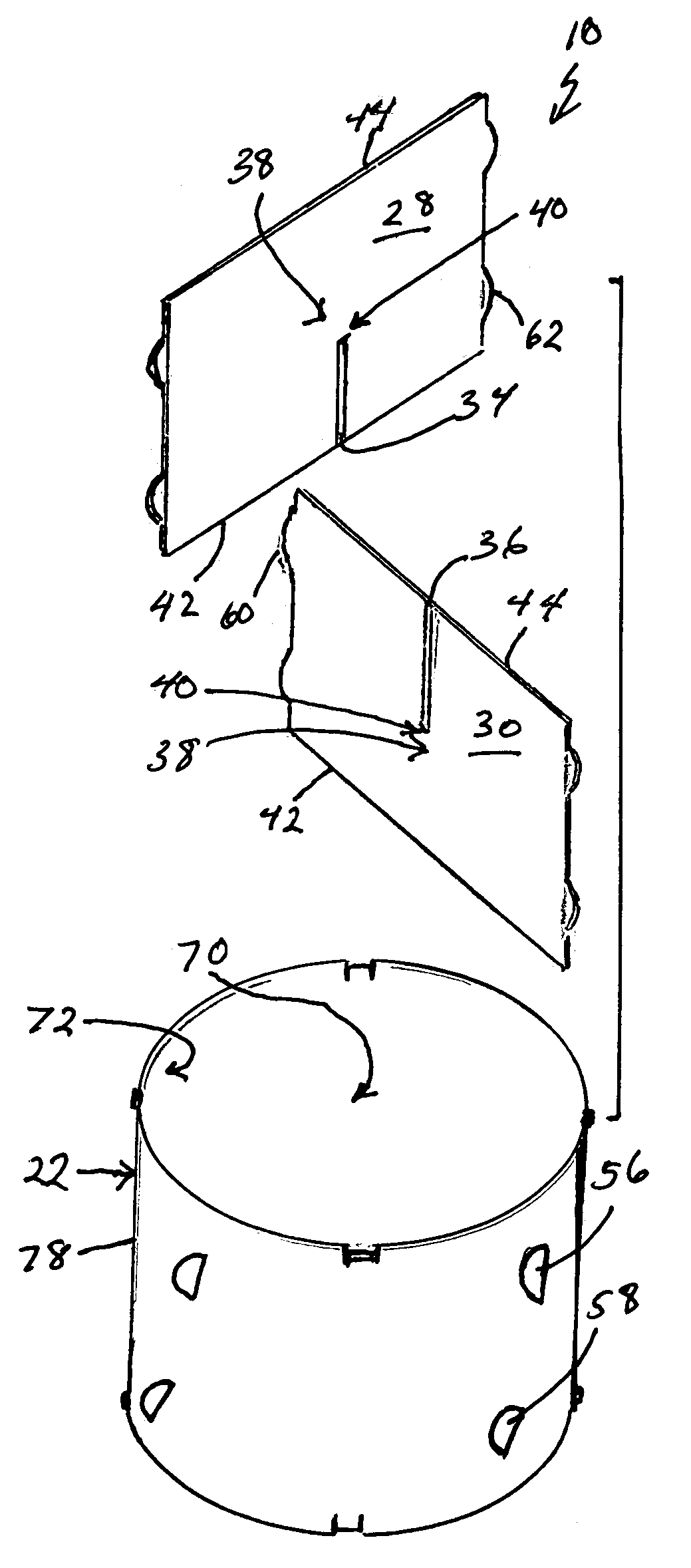
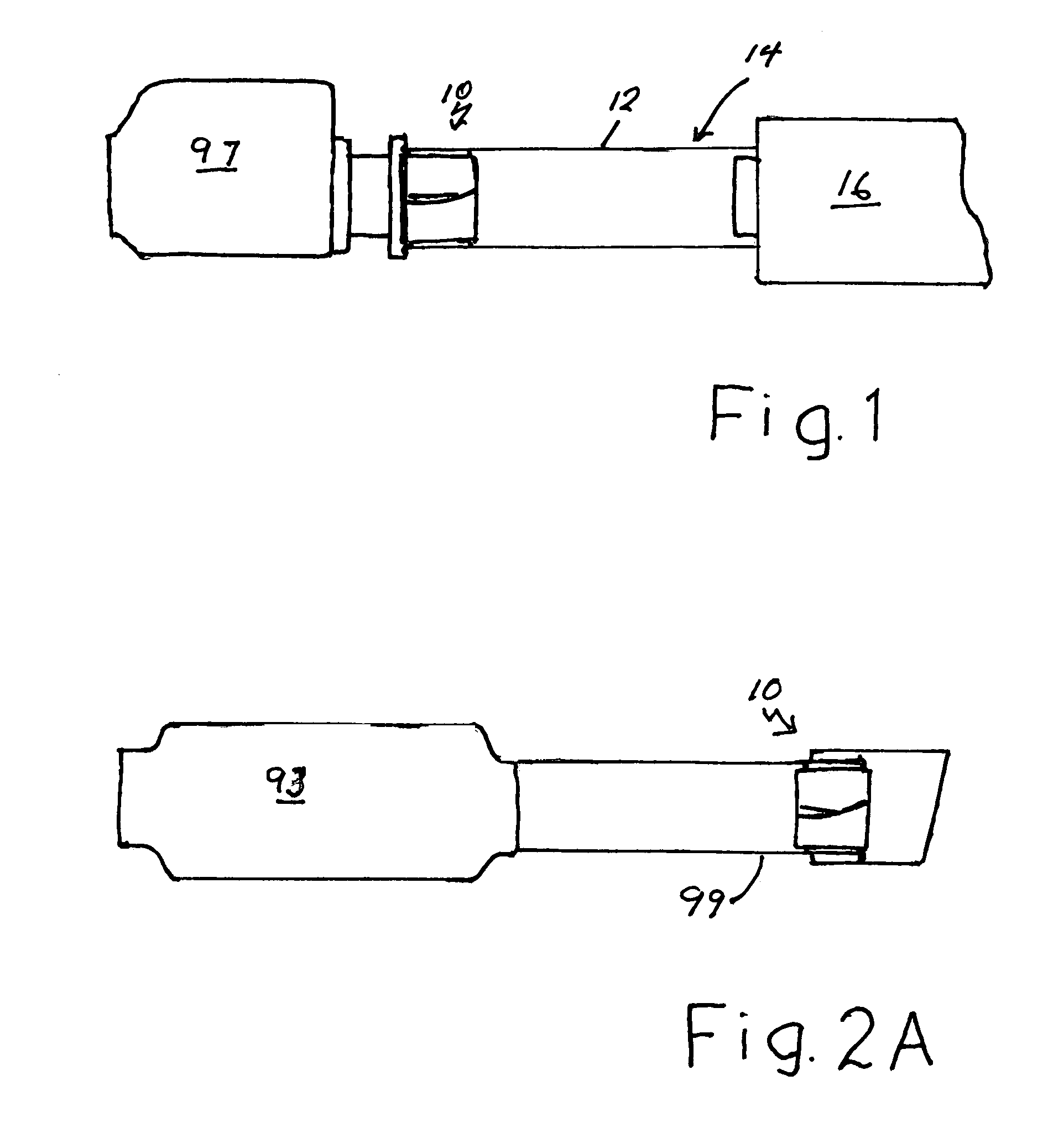
[0042]Referring to the drawings, the swirling device of the present invention is generally designated by the numeral 10. The device 10 is sized to fit inside an intake passageway or duct 12 of an intake subsystem 14 of an internal combustion engine (not shown). The passageway 12 leads to a fuel introduction subsystem 16 which may be a fuel injection subsystem, as shown, or a carburetor. The passageway is thus used for delivery of intake air to the fuel injection subsystem 16 from the air filter box 97.

[0043]FIG. 2A shows the device 10 mounted in an exhaust passageway or pipe 99. The tailpipe 99 is attached to a catalytic converter 93 which receives the exhaust gases from the muffler (not shown) and from the engine (not shown). The device provides a swirl to the exhaust gases resulting in a vortex shaped flow stream thereby drawing out the exhaust gases from the exhaust system.

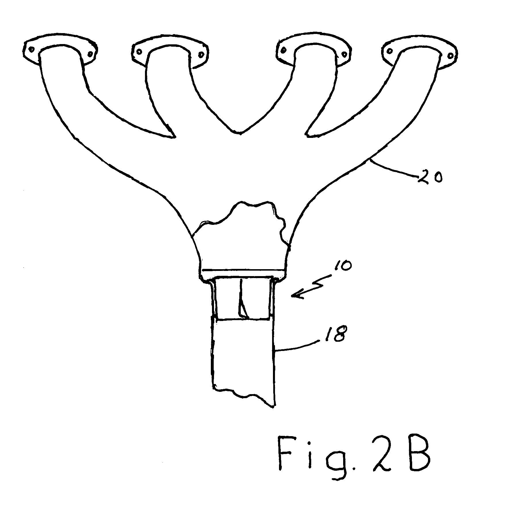
[0044]FIG. 2B shows the device 10 mounted in another type of exhaust passageway or pipe 18. The exhaust pipe...


PUM


Abstract

The device includes a pair of flat planar vanes securely mounted within a cylindrical housing. The vanes have a medial slit extending from the center to a longitudinal end of the vane. The vanes are interconnected at the slits so that they are in criss-cross positioning. The vanes are axially angled so that when positioned in an intake air duct the vanes impart a swirling motion to the air entering the engine providing more complete mixing of the air and fuel and when positioned in an exhaust passageway the vanes impart a swirling motion to the exhaust gases exiting the engine providing scavenging of the exhaust gases.

Description

BACKGROUND OF THE INVENTION[0001]The invention relates generally to intake and exhaust systems for internal combustion engines of the type conventionally used in motor vehicles. More specifically, the invention relates to intake and exhaust system components and accessories used to provide improved fuel economy and performance. The invention also more specifically relates to such components and accessories which provide enhanced combustion efficiency by improving mixing of the air and fuel entering the engine or by improving exhaust gas flow through the exhaust system.[0002]In a conventional internal combustion engine's intake system, the fluid flow which moves adjacent the walls of the intake passageway i.e., laminar fluid flow, typically includes a substantial amount of gasoline that is not atomized. Fuel that is not atomized does not readily combust. Thus, incomplete atomization of the fuel in the fluid flow hinders complete combustion of the fluid. This laminar flow consequently...

Claims


Application Information

Patent Timeline
Patent Type & Authority Patents(United States)
IPC IPC(8): F02M29/00B21K3/00F01N13/08
CPCF01N13/08F02B31/04Y02T10/146F01N2260/06Y02T10/12
Inventor KIM, JAY S.
Owner KIM JAY S
Why Eureka
Try Eureka