Dissolvable downhole tool, method of making and using

a technology of dissolvable downhole tools and tools, applied in the direction of fluid removal, borehole/well accessories, coatings, etc., can solve the problems that even in a deformed state, their presence, can still be undesirabl

Active Publication Date: 2010-11-25
BAKER HUGHES INC
View PDF5 Cites 154 Cited by
  • Summary
  • Abstract
  • Description
  • Claims
  • Application Information

AI Technical Summary

Benefits of technology

[0002]Disclosed herein is a dissolvable downhole tool. The tool includes, a dissolvable body constructed of at least two materials and at least one of the at least two materials is a reactive materia

Problems solved by technology

Although such tools work as intended, their presence

Method used


Image

  • Dissolvable downhole tool, method of making and using
  • Dissolvable downhole tool, method of making and using
  • Dissolvable downhole tool, method of making and using

Examples


Embodiment Construction

[0012]A detailed description of one or more embodiments of the disclosed apparatus and method are presented herein by way of exemplification and not limitation with reference to the Figures.

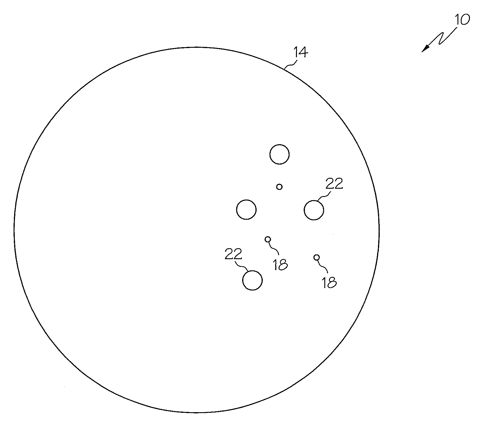
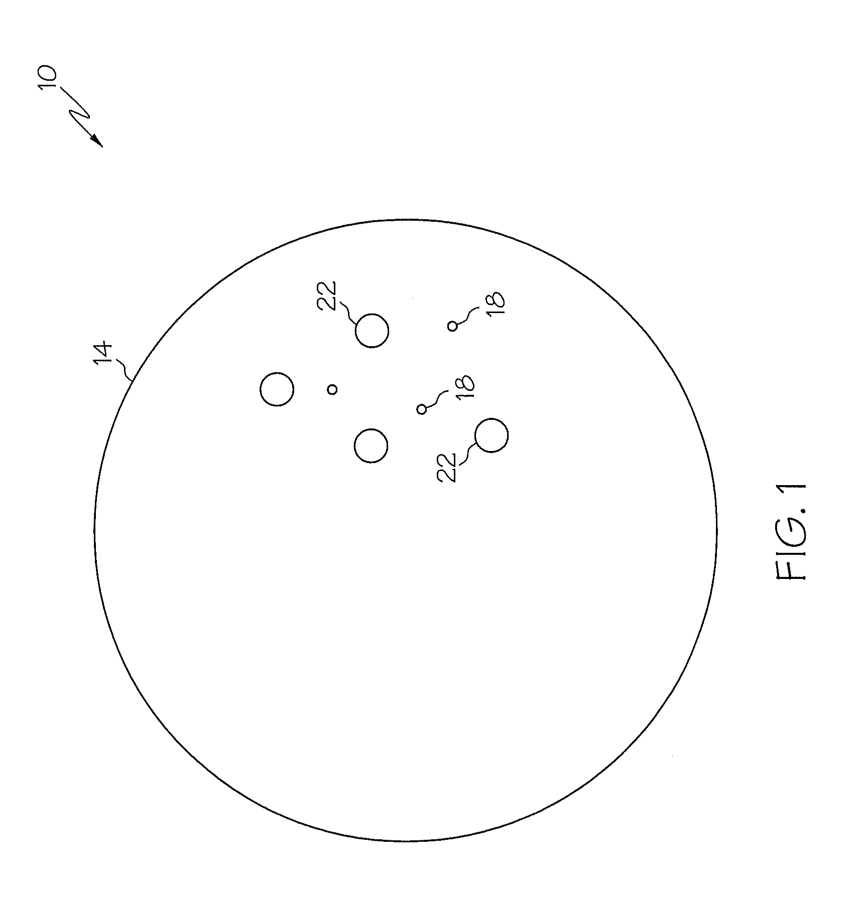
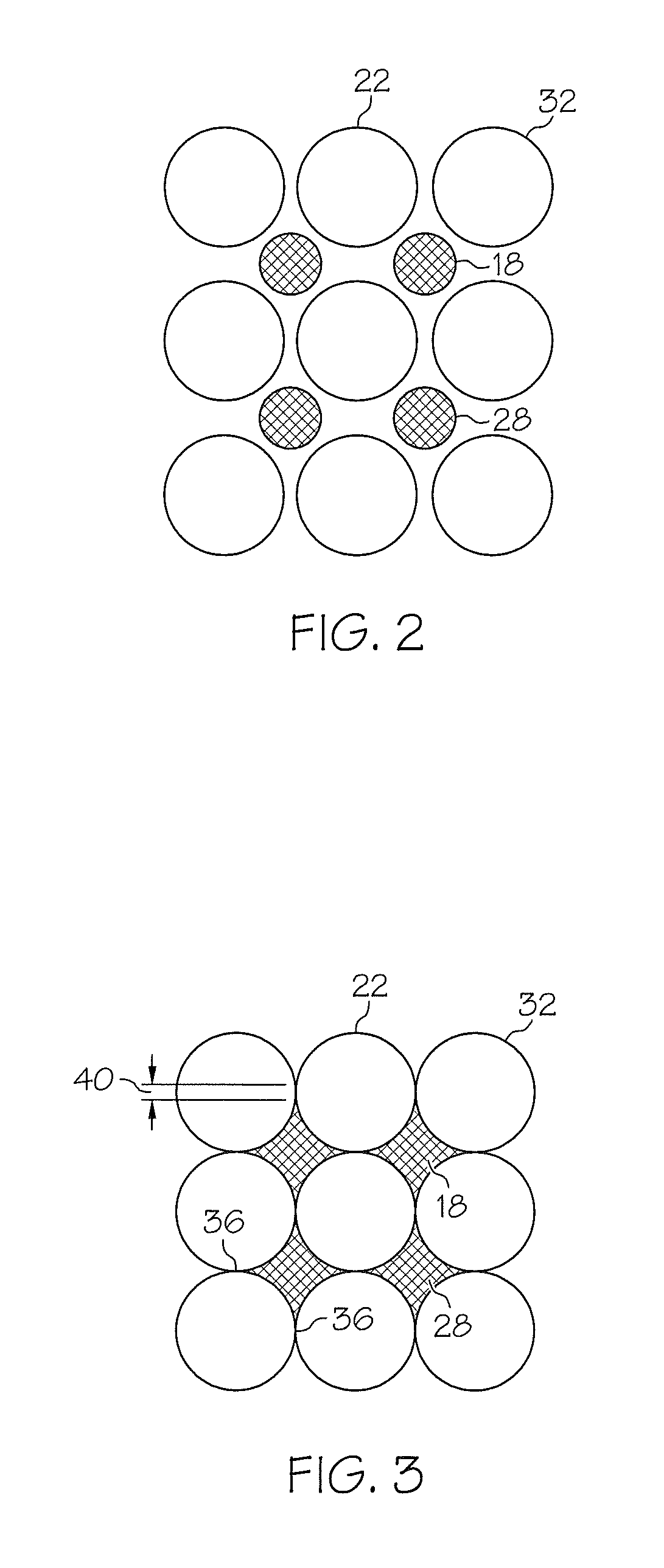
[0013]Referring to FIG. 1, a cross-sectional view of an embodiment of a dissolvable downhole tool, depicted in this embodiment as a tripping ball, is illustrated at 10. Alternate embodiments of the downhole tool include 10, ball seats and cement shoes, for example, as well as other tools whose continued downhole presence may become undesirable. The downhole tool 10 includes a body 14 constructed of at least two reactive materials with this particular embodiment disclosing specifically two reactive materials 18, 22. The first reactive material 18 being much more reactive than the second reactive material 22. These reactivities being defined when the reactive materials 18, 22 are in an environment wherein they are reactive (as will be described in detail below), such as may exist in a downhole envi...


PUM


Abstract

Disclosed herein is a dissolvable downhole tool. The tool includes, a dissolvable body constructed of at least two materials and at least one of the at least two materials is a reactive material, and a first material of the at least two materials being configured to substantially dissolve the dissolvable body and a second material configured to control reaction timing of the first material.

Description

BACKGROUND[0001]In the subterranean drilling and completion industry there are times when a downhole tool located within a wellbore becomes an unwanted obstruction. Accordingly, downhole tools have been developed that can be deformed, by operator action, for example, such that the tool's presence becomes less burdensome. Although such tools work as intended, their presence, even in a deformed state can still be undesirable. Devices and methods to further remove the burden created by the presence of unnecessary downhole tools are therefore desirable in the art.BRIEF DESCRIPTION[0002]Disclosed herein is a dissolvable downhole tool. The tool includes, a dissolvable body constructed of at least two materials and at least one of the at least two materials is a reactive material, and a first material of the at least two materials being configured to substantially dissolve the dissolvable body and a second material configured to control reaction timing of the first material.[0003]Further d...

Claims


Application Information

Patent Timeline
IPC IPC(8): E21B41/00E21B34/06B05D7/02B05D1/36
CPCE21B41/00E21B23/00E21B29/00
Inventor HOLMES, KEVIN C.
Owner BAKER HUGHES INC
Why Eureka
Try Eureka