
Power seat track drive assembly

a technology for driving assembly and seat, which is applied in the direction of machine support, movable seat, gearing, etc., can solve the problem of important packaging of the gearbox

Inactive Publication Date: 2010-12-23
INTIER AUTOMOTIVE INC
View PDF20 Cites 59 Cited by
  • Summary
  • Abstract
  • Description
  • Claims
  • Application Information

AI Technical Summary

Benefits of technology

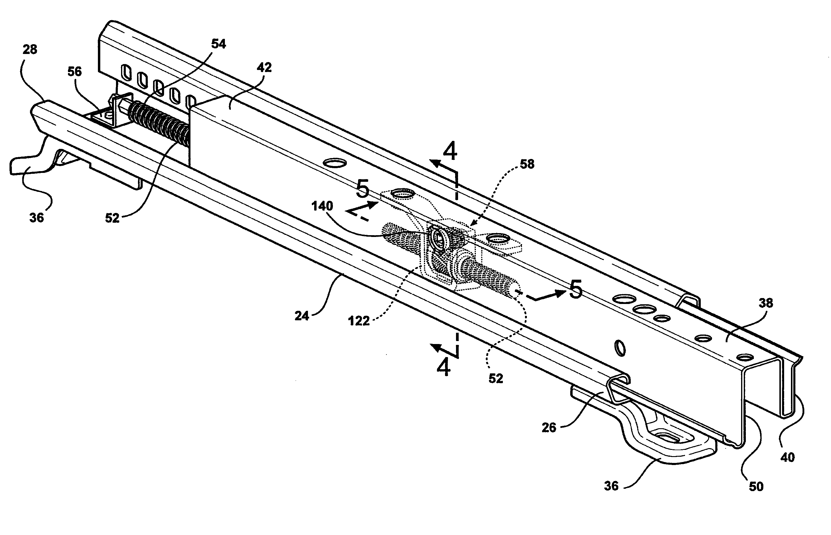
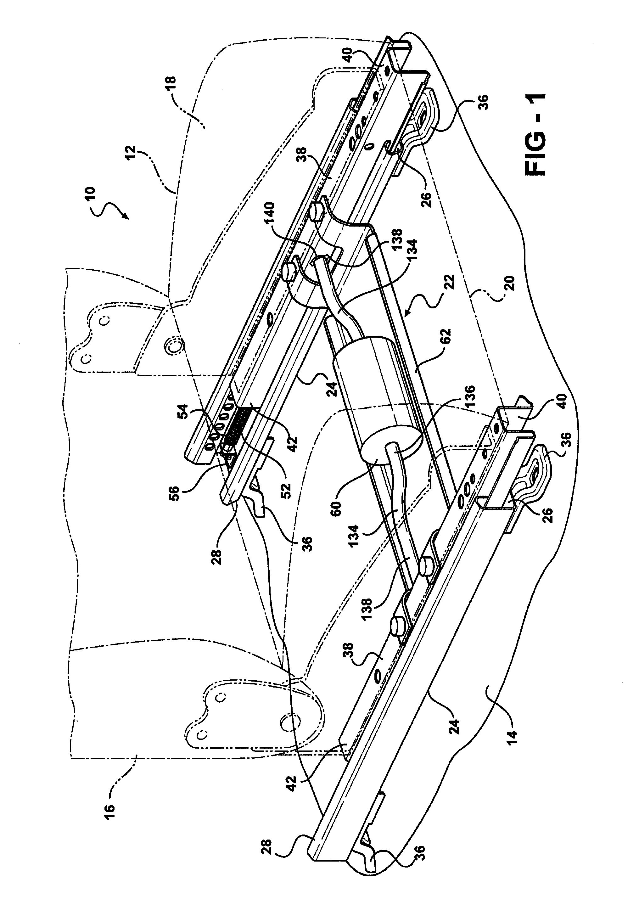
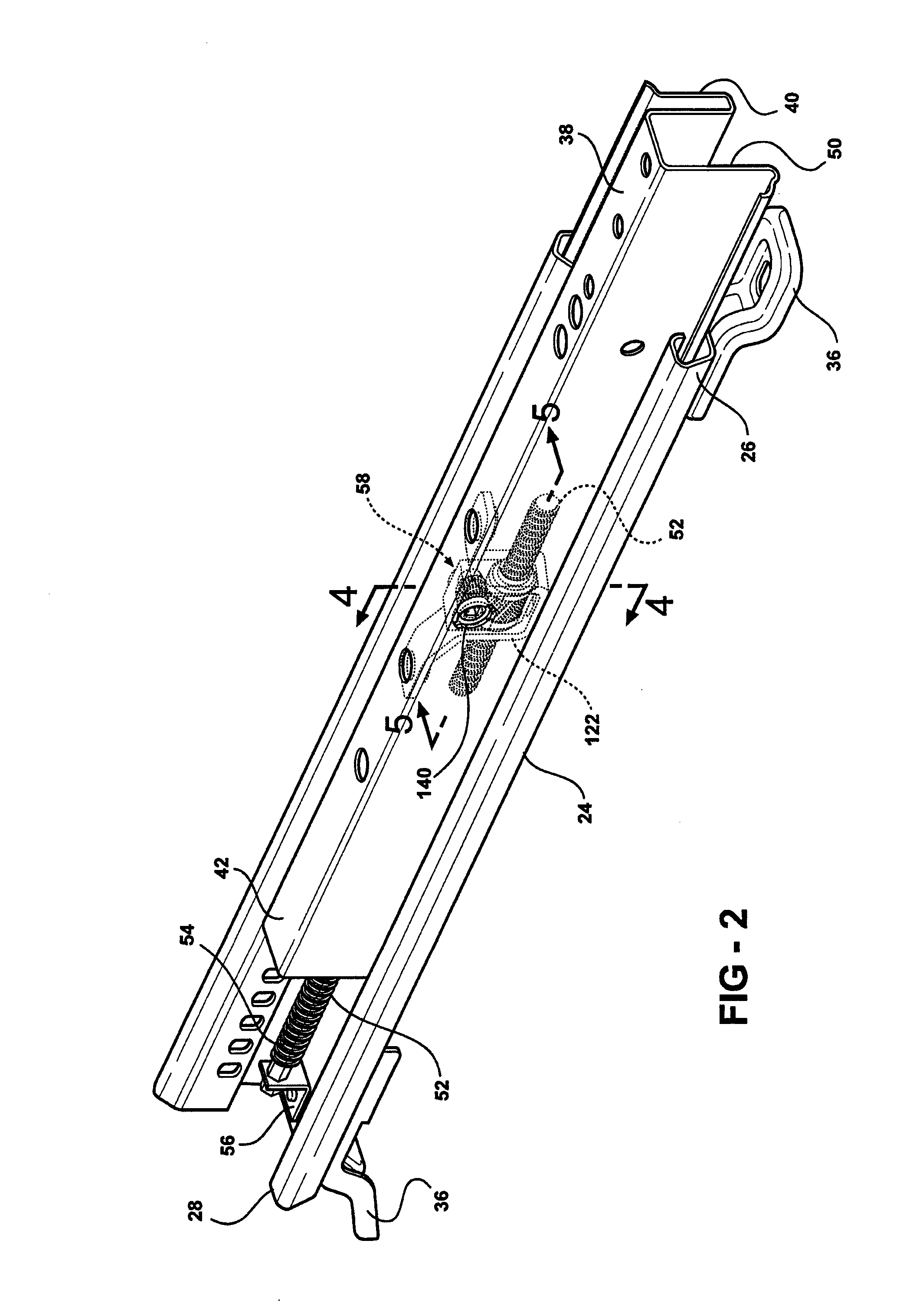
[0011]According to yet another aspect of the invention, a power seat track assembly is provided for moving a seat fore and aft. A fixed track is adapted to be mounted to the floor and a movable track slidably engages the fixed track. A threaded screw is fixedly secured to the fixed track. A gear is rotatably disposed about the threaded screw and the gear includes a geared outer surface. A housing includes a bore and a lower arcuate surface having an opening therethrough. A worm is rotatably disposed within the bore of the housing and extends between a bearing end and a driven end. The worm includes a threaded outer surface that protrudes through the opening in the lower arcuate surface of the housing and threadably engages the geared outer surface of the gear. A generally U-shaped retainer strap partially surrounds the gear and is adapted to couple the housing and gear together to align and preload the worm and the gear. A generally U-shaped bracket is adapted to be fixedly secured to the movable track. The gear, housing, worm, and retainer strap are disposed within the bracket and the threaded screw passes through a pair of openings in the bracket. A drive is operatively coupled to the driven end of the worm such that rotation of the worm causes the gear to rotate and travel along the threaded screw which urges the bracket and therefore the movable track fore and aft.

Problems solved by technology

Because the longitudinal channel between the upper and lower tracks is limited, packaging of the gearbox is an important issue.

Method used


Image

  • Power seat track drive assembly
  • Power seat track drive assembly
  • Power seat track drive assembly

Examples


second embodiment

[0053]Referring to FIG. 8, in the invention, opposite front 144 and rear 146 sides of the housing 78 are shown to include at least one outwardly extending crush rib 148. The crush ribs 148 compressingly deform upon engagement with the sides 126 of the bracket 122 to prevent clunk or longitudinal movement of the drive assembly 58 therebetween when the motor 60 reverses direction.

third embodiment

[0054]Referring to FIGS. 9 and 10, in the invention, a generally U-shaped spring clip 150 is inserted through a slot 152 in the upper track 38 and is disposed between the inboard, inner side wall 46 of the upper track 38 and the end plug 98. The spring clip 150 axially preloads the worm 82 against the gear 66 while also ensuring that the drive assembly 58 is snug laterally between the inner walls 46, 48 of the upper track 38. In addition, the spring clip 150 prevents lateral clunk or lateral movement of the drive assembly 58 between the inner walls 46, 48 of the upper track 38 when the motor 60 reverses direction.

fourth embodiment

[0055]Referring to FIGS. 11 and 12, in the invention, each upright portion 110 of the retainer strap 68 includes a pair of preformed anti-rattle ears 154 extending generally upwardly therefrom. The ears 154 deflect upon contact with the inner side walls 46, 48 and / or the upper wall 44 of the upper track 38 to prevent lateral and upward movement of the drive assembly 58 within the channel 50 during operation of the seat track assembly 22.


PUM


Abstract

An adjustment mechanism is disclosed for moving a movable member relative to a fixed member. A threaded screw is fixedly secured to the fixed member. A gear is rotatably disposed about the threaded screw. A housing includes a bore and an opening in a lower surface. A rotatably driven worm is disposed within the bore and includes a threaded outer surface that protrudes through the opening in the lower surface of the housing and threadably engages the gear. A generally U-shaped retainer strap partially surrounds the gear and is adapted to couple the housing and gear together to align and preload the worm and gear. A generally U-shaped bracket is adapted to be fixedly secured to the movable member, wherein the gear, housing, worm, and retainer strap are disposed within the bracket and the threaded screw passes through a pair of openings in the bracket.

Description

CROSS REFERENCE TO RELATED APPLICATION[0001]This application claims priority to and all the benefits of U.S. Provisional Application Ser. No. 60 / 853,630, filed on Oct. 23, 2006 and entitled “Power Seat Track Drive Assembly.”BACKGROUND OF THE INVENTION[0002]1. Field of the Invention[0003]The invention relates to a seat track for an automotive vehicle seat assembly. More particularly, the invention relates to a power seat track drive assembly for providing fore and aft movement of a seat assembly along a floor of an automotive vehicle.[0004]2. Description of Related Art[0005]Automotive vehicles include seat assemblies for supporting seat occupants within a passenger compartment of the vehicle. Typically, seat assemblies include a generally horizontal seat cushion spaced above a floor of the vehicle and a generally vertical or upright seat back. The seat back is commonly operatively coupled to the seat cushion to allow for selective pivotal adjustment of the seat back relative to the s...

Claims


Application Information

Patent Timeline
Patent Type & Authority Applications(United States)
IPC IPC(8): B60N2/07F16H25/20B60N2/90
CPCB60N2/067B60N2/0705F16H1/16Y10T74/18576F16H2025/209F16H25/24B60N2002/0236F16H25/20B60N2/02253B60N2/06
Inventor WEBER, JAMES L.
Owner INTIER AUTOMOTIVE INC
Learn More