Hydraulic pump

Inactive Publication Date: 2011-01-27
ULTIMATE PUMP
View PDF10 Cites 0 Cited by
  • Summary
  • Abstract
  • Description
  • Claims
  • Application Information

AI Technical Summary

Benefits of technology

[0008]The pump according to the invention has several technical advantages. Relative to conventional pump structures, it is easy to manufacture as it has a total of nineteen parts in the illustrated embodiment, of only seven different types: one drive shaft, eight pistons, two cylinder block inserts, two cylinder block casings, two

Problems solved by technology

This sharply drives up their cost of manufacture.
But this arrangement heretofore has not been applied to situations in which a

Method used


Image

  • Hydraulic pump
  • Hydraulic pump
  • Hydraulic pump

Examples


Example

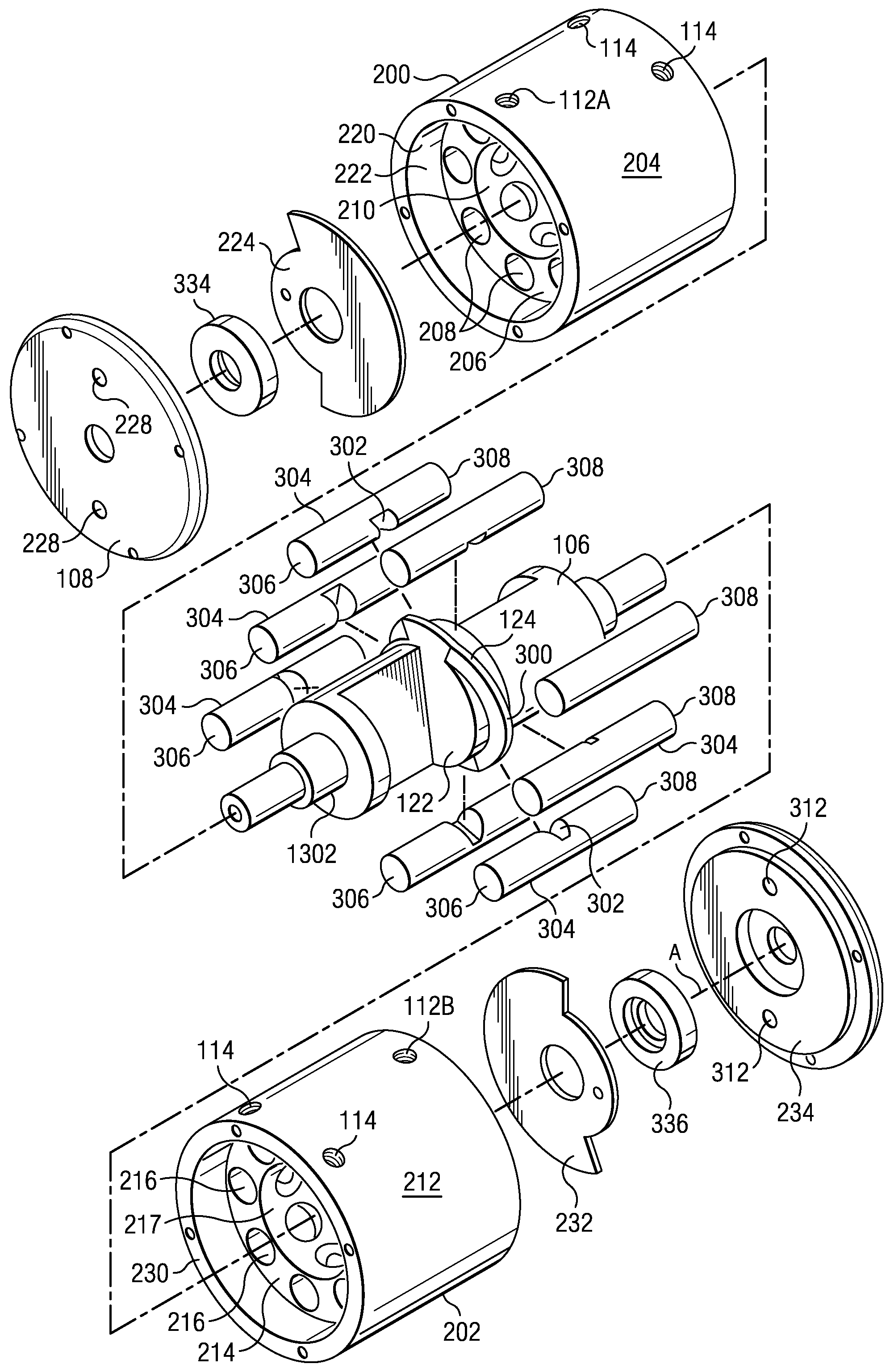
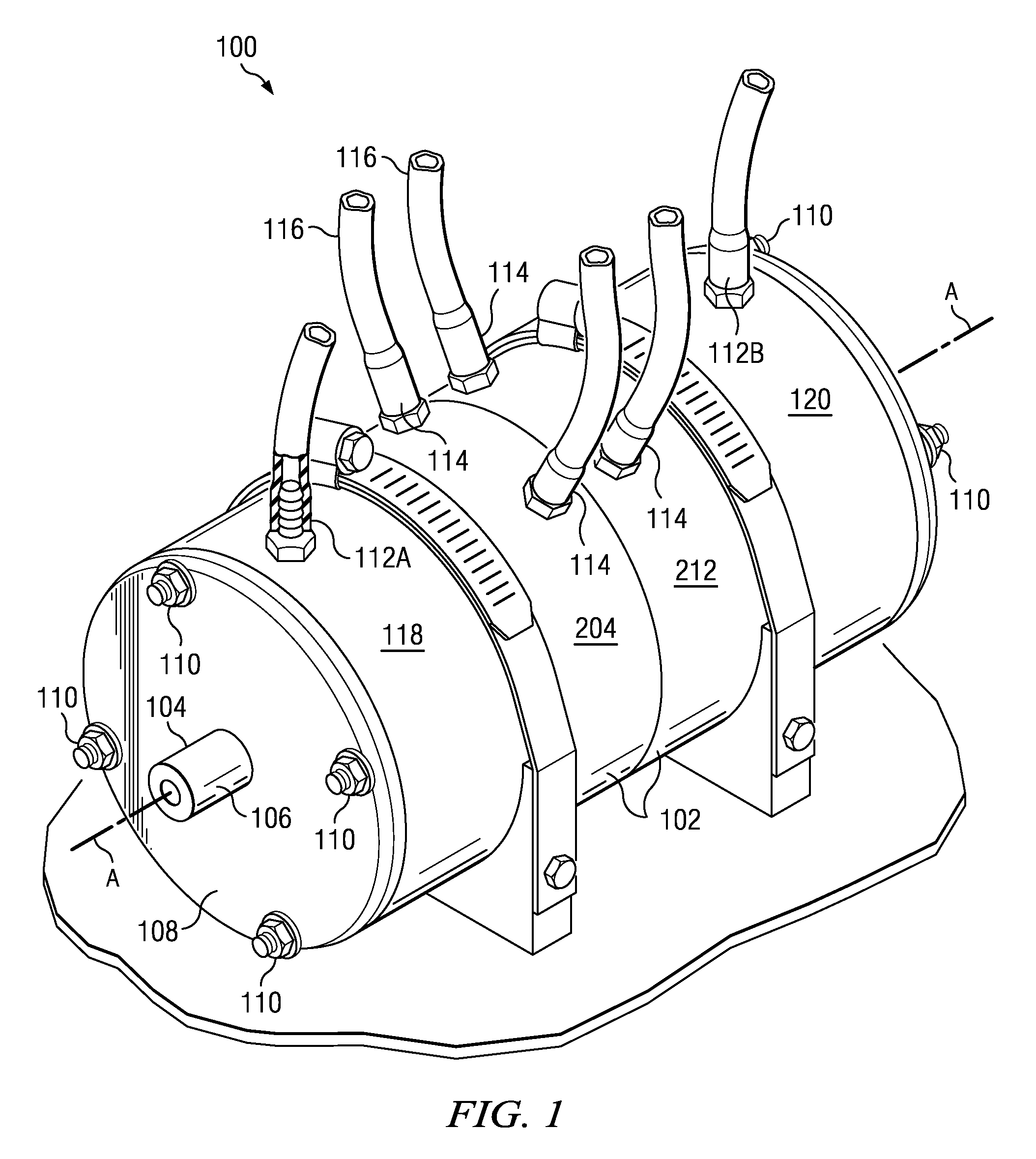
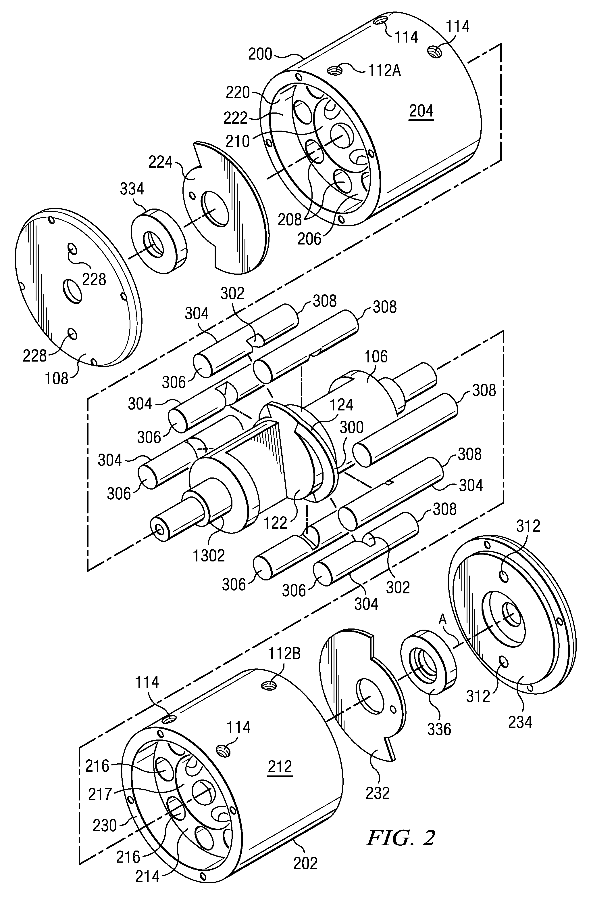
[0025]Referring first to FIG. 1, an isometric view is shown of a pump indicated generally at 100 according to a first embodiment of the invention. The pump 100 has an external cylindrical casing 102 which is formed around an axis A. One end 104 of a drive shaft 106 extends beyond an end cap 108, which in this embodiment is bolted to the casing 102 with through-bolts 110 which extend the entire axial length of the pump 100 and are parallel to axis A. Four bolts 110 are shown in the illustrated embodiment; for embodiments meant for higher-pressure applications, the number of bolts 110 could be increased. The drive shaft 106 is generally aligned with axis A although is not radially symmetrical throughout, as will be described below.

[0026]The pump 100 has at least one, and preferably two, outlet ports 112A and 112B through which a fluid is pumped. In the illustrated embodiment, the pump 100 further has several inlet ports 114 and these preferably are capable of introducing a greater vol...


PUM


Abstract

A pump has an axial drive shaft with a cam fence that extends radially outwardly from an axis of the drive shaft. The cam fence axially displaces, in respective cylinders, each of a plurality of elongate pistons arranged in parallel to and around the axis and angularly spaced apart from each other. The axial position of an outer margin of the cam fence varies as a function of its radial angle with the axis. In one part of the operation of the pump, a piston is withdrawn to uncover a radial inlet port to draw fluid into the cylinder from an internal reservoir volume formed in the drive shaft. In a second part of the operation, the drive shaft is further rotated to open a cylinder end port by means of a rotary valve and closing the side port of the cylinder with a portion of the drive shaft body. In a third part of the operation, the piston is advanced to push fluid out of the cylinder end port into an output chamber. The pump is double-ended such that opposed ends of any piston are drawing in fluid, and pushing out fluid, at the same time.

Description

BACKGROUND OF THE INVENTION[0001]Conventional pumps have many parts and usually include o-rings or other seals. This sharply drives up their cost of manufacture. Improvements could therefore be made in providing a pump that is simpler in design and less costly than conventional offerings.[0002]An internal combustion engine has been proposed by which a set of pistons and cylinders, disposed in parallel to a central axis but radially displaced therefrom, provide power to a central shaft by means of a cam drive. See United States Patent Application Publication No. US 2008 / 0105222 A1 to Kubes et al. But this arrangement heretofore has not been applied to situations in which a central drive shaft supplies rotational power instead of receiving it, and in which the pumping of a fluid is the desired work.SUMMARY OF THE INVENTION[0003]According to one aspect of the invention, a hydraulic pump includes an axial drive shaft with a radially extending cam fence. The axial position of an outer ma...

Claims


Application Information

Patent Timeline
IPC IPC(8): F01B13/04
CPCF04B1/124F04B5/02F04B1/128
Inventor FLEGEL, MICHAEL W.
Owner ULTIMATE PUMP
Why Eureka
Try Eureka