Tubular LED illuminating device with 360-degree radiation

a technology of led illuminating device and rotary axis, which is applied in the direction of lighting and heating apparatus, point-like light source, lighting support device, etc., can solve the problem that the type of light field is not suitable for illumination

Inactive Publication Date: 2011-01-27
FOXSEMICON INTEGRATED TECH INC
View PDF8 Cites 73 Cited by
  • Summary
  • Abstract
  • Description
  • Claims
  • Application Information

AI Technical Summary

Problems solved by technology

However, this type of light field is not suitable for illumination, particularly when the tubular LED illuminating device is constructed to replace the conventional fluorescent tube, which has a 360-degree light field distribution.

Method used


Image

  • Tubular LED illuminating device with 360-degree radiation
  • Tubular LED illuminating device with 360-degree radiation
  • Tubular LED illuminating device with 360-degree radiation

Examples


Embodiment Construction

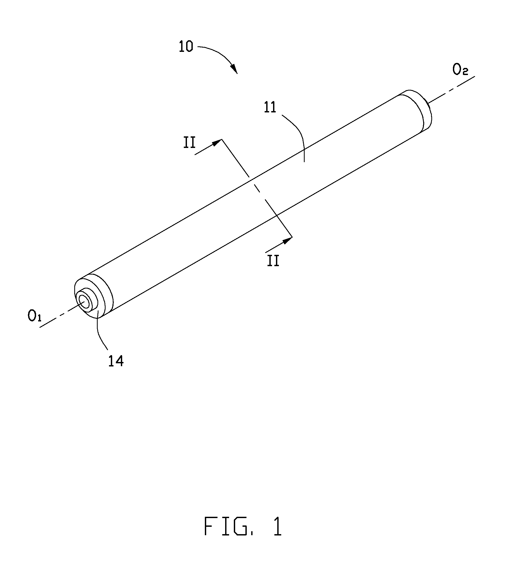
[0014]Reference will now be made to the drawings to describe the embodiments of the present tubular LED illuminating device in detail.

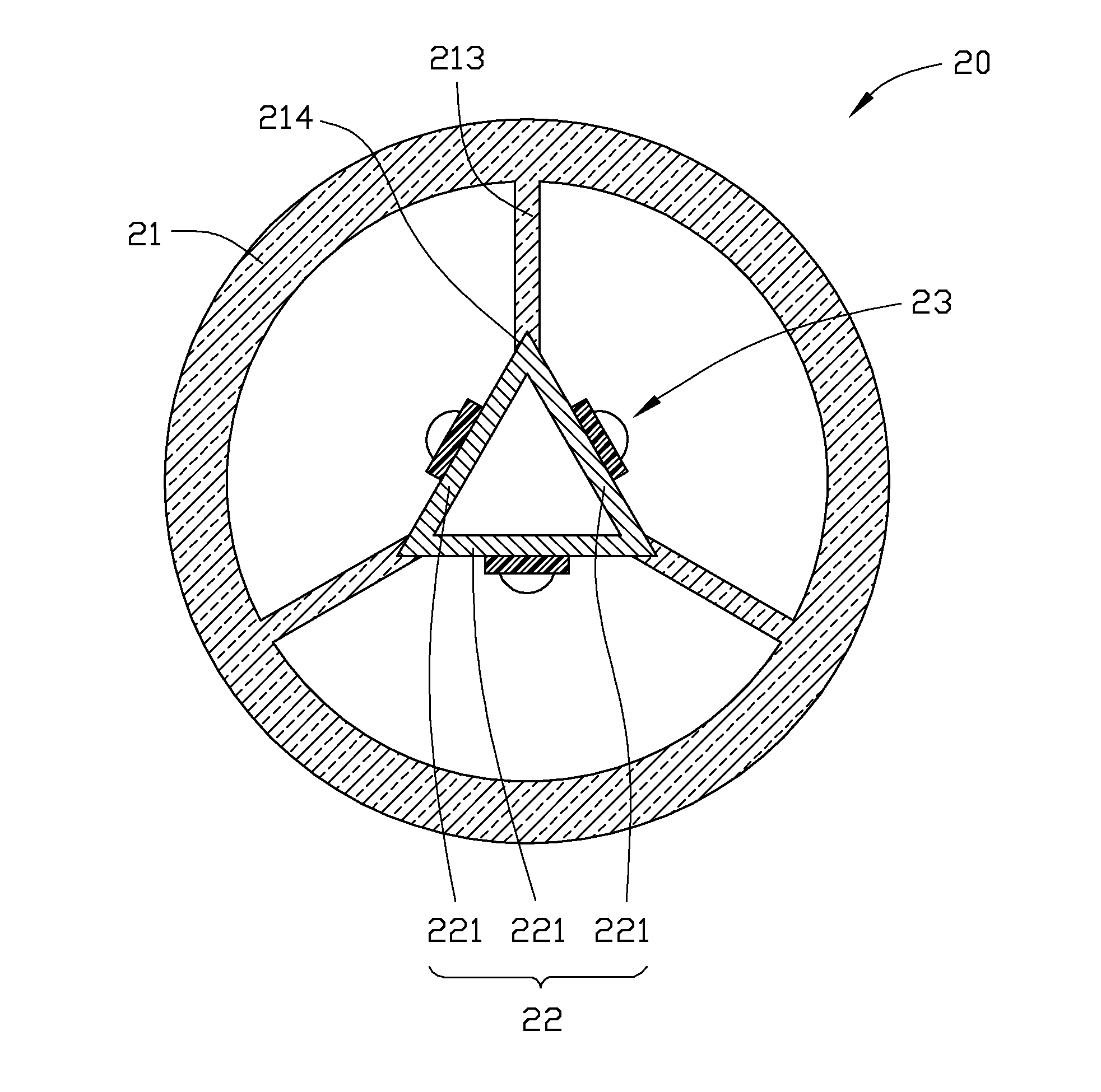
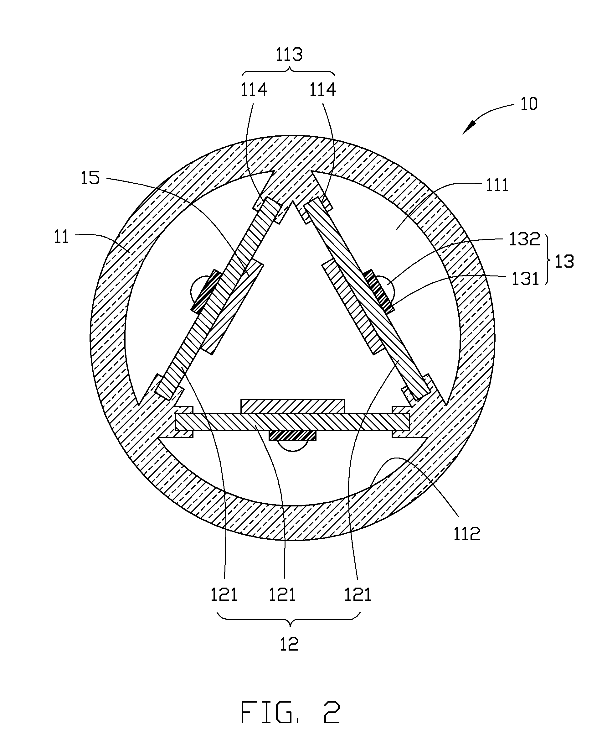
[0015]Referring to FIGS. 1 and 2, a tubular LED illuminating device 10 according to a first exemplary embodiment of the present disclosure is provided. The illuminating device 10 includes a tubular shell 11, a supporting frame 12 and a plurality of (i.e., three) elongated light emitting units 13.

[0016]The shell 11 defines a chamber 111 therein and has an inner surface 112. The inner surface 112 forms three elongate protrusions 113 protruding radially inwardly from the inner surface 112 of the shell 11 and extending along a direction parallel to an axial direction (i.e., O1-O2 direction) of the shell 11. In the present embodiment, the protrusions 113 are integrally formed with the shell 11 and arranged symmetrically about the circumferential direction of the shell 11. An extremity end of each of the protrusions 113 defines two elongate recesses 114 ext...


PUM


Abstract

A tubular LED illuminating device comprises a tubular shell, a supporting frame and a plurality of light emitting units. An inner surface of the shell forms a plurality of elongate protrusions extending along a direction parallel to an axial direction of the shell. Each of the protrusions defines at least one elongate recess extending along the axial direction of the shell. The supporting frame is received in the shell and comprises at least three supporting plates. Two opposite edges of each supporting plate are respectively embedded in the adjacent recesses of different protrusions. The light emitting units are arranged on the at least three supporting plates, and light emitted from the light emitting units emits out through the shell and has a radiation angle of 360 degrees.

Description

BACKGROUND[0001]1. Technical Field[0002]The present disclosure generally relates to an LED illuminating device, and more particularly to a tubular LED illuminating device which has a radiation angle about 360 degrees, whereby the tubular LED illuminating device can have a light field distribution similar to that of a conventional fluorescent tube.[0003]2. Discussion of Related Art[0004]With the continuing development of scientific technology, light emitting diodes (LEDs) have been widely used in illumination devices to substitute for conventional cold cathode fluorescent lamps (CCFL) and conventional fluorescent tubes due to their high brightness, long life-span, and wide color gamut.[0005]Conventional tubular LED illuminating devices incorporating LEDs generally generate butterfly-type light fields or have a radiation angle about 120 degrees. Referring to FIG. 6, a radiation angle of a conventional tubular LED illuminating device which is about 120 degrees is shown. However, this t...

Claims


Application Information

Patent Timeline
Patent Type & Authority Applications(United States)
IPC IPC(8): F21S4/00
CPCF21K9/17F21Y2111/005F21Y2111/001F21Y2101/02F21K9/27F21Y2107/00F21Y2107/30F21Y2115/10
Inventor LAI, CHIH-MING
Owner FOXSEMICON INTEGRATED TECH INC
Why Eureka
Try Eureka