LED light fixture

a technology of led light fixtures and led tubes, which is applied in the direction of semiconductor devices for light sources, lighting and heating apparatus, and support devices for lighting and heating devices

Inactive Publication Date: 2011-02-17
LUMENESCENT
View PDF3 Cites 58 Cited by
  • Summary
  • Abstract
  • Description
  • Claims
  • Application Information

AI Technical Summary

Benefits of technology

[0011]One embodiment of the present invention is an LED light fixture connectible to an electrical supply located external to the light fixture. The fixture has a pair of opposed end caps or supports connected together by an elongated member. Each end cap has a plurality of female connectors thereon that are aligned with corresponding female connectors on the opposite end cap. The female connectors removably receive male connectors located at the opposite ends of an LED light tube. The female connectors are oriented on the end caps to shine the light from each LED light tube downward at a preselected angle. In one version, the female connectors are movably mounted to the end caps allowing the user to manually move the connectors to a desired angle to direct the light from each light tube downward at different angles relative to the vertical.

Problems solved by technology

As a result, much of the light is lost since the light reflects against the ceiling or fixture.
While fluorescent tubes are more efficient in generating light as compared to an incandescent bulb, the tubes have to be frequently replaced requiring substantial maintenance cost.

Method used


Image

  • LED light fixture
  • LED light fixture
  • LED light fixture

Examples


Embodiment Construction

[0026]For the purposes of promoting an understanding of the principles of the invention, reference will now be made to the embodiments illustrated in the drawings and specific language will be used to describe the same. It will nevertheless be understood that no limitation of the scope of the invention is thereby intended, such alterations and further modifications in the illustrated device, and such further applications of the principles of the invention as illustrated therein being contemplated as would normally occur to one skilled in the art to which the invention relates.

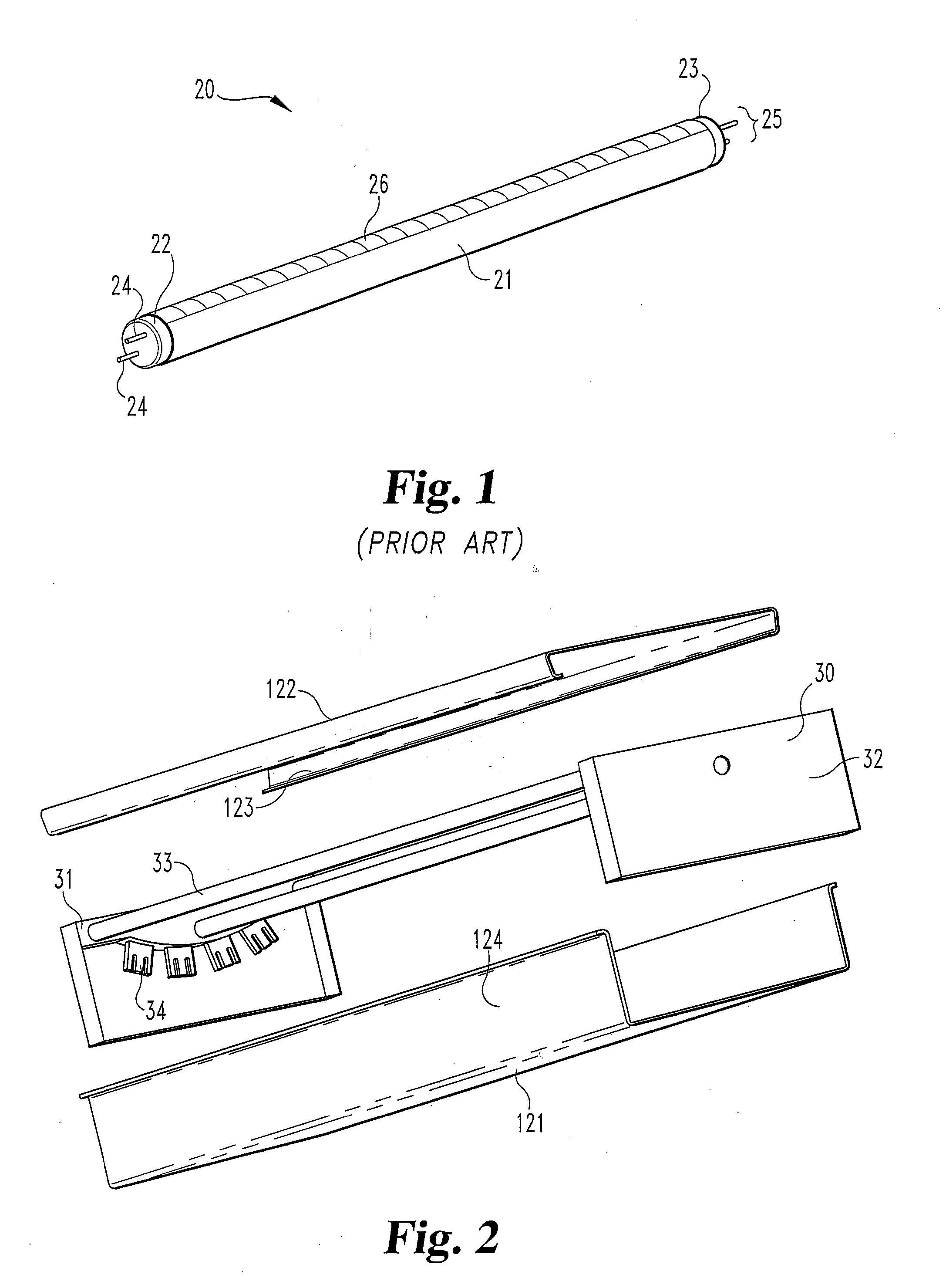
[0027]Referring now more particularly to FIG. 1, there is shown a commercially available LED light tube 20 having a cylindrical tube 21 with a pair of end covers 22 and 23 affixed thereto. A first pair of male connectors 24 extend outwardly from end cover 22 and a second pair of male connectors 25 extend outwardly from cover 23. Connectors 24 and 25 are connected to a plurality of LEDs mounted within tube 21 wh...


PUM


Abstract

A light fixture for holding LED tubes. A pair of end caps are held together by an elongated member. Female connectors mounted to the end caps receive the male connectors of the LED light tubes. The female connectors are mounted to the end caps allowing for the pre-selection of the angle of illumination.

Description

BACKGROUND OF THE INVENTION[0001]1. Field of the Invention[0002]The present invention relates generally to the field of light fixtures.[0003]2. Description of the Prior Art[0004]Fluorescent light tubes have opposite male connector ends removably mounted to female connectors referred to as tombstones. Tombstones are fixedly mounted to a light fixture generally suspended from a ceiling or recessed into the ceiling. The male connectors are slid into the female slots and the light tubes are then locked or rotated to mount the fluorescent tube to the light fixture. Fluorescent tubes radiate light 360 degrees around the tube. As a result, much of the light is lost since the light reflects against the ceiling or fixture. While fluorescent tubes are more efficient in generating light as compared to an incandescent bulb, the tubes have to be frequently replaced requiring substantial maintenance cost.[0005]LED (light emitting diode) light tubes are available and have male connector ends ident...

Claims


Application Information

Patent Timeline
Patent Type & Authority Applications(United States)
IPC IPC(8): F21V7/00F21S4/00
CPCF21V15/015F21V19/0085F21Y2103/003F21Y2101/02F21V19/04F21Y2103/10F21Y2115/10
Inventor PYLE, ALAN R.
Owner LUMENESCENT
Why Eureka
Try Eureka