
Shutter for a fiber optic component and a fiber optic component including the shutter

Inactive Publication Date: 2011-02-17
COMMSCOPE INC
View PDF8 Cites 41 Cited by
  • Summary
  • Abstract
  • Description
  • Claims
  • Application Information

AI Technical Summary

Problems solved by technology

Such plugs, while effective, may be dropped and lost when being inserted or removed and may not be readily available when needed.
However, such shutters generally include a spring for biasing the cover toward a closed position and / or a latch for securing the cover in a closed position which makes these covers relatively complex and expensive to manufacture.
Moreover, connectors having covers biased toward a closed position by a spring must be held open against the force of the spring when an operator attempts to load the receptacle with a connector, which can be cumbersome during connector installations.

Method used


Image

  • Shutter for a fiber optic component and a fiber optic component including the shutter
  • Shutter for a fiber optic component and a fiber optic component including the shutter
  • Shutter for a fiber optic component and a fiber optic component including the shutter

Examples


second embodiment

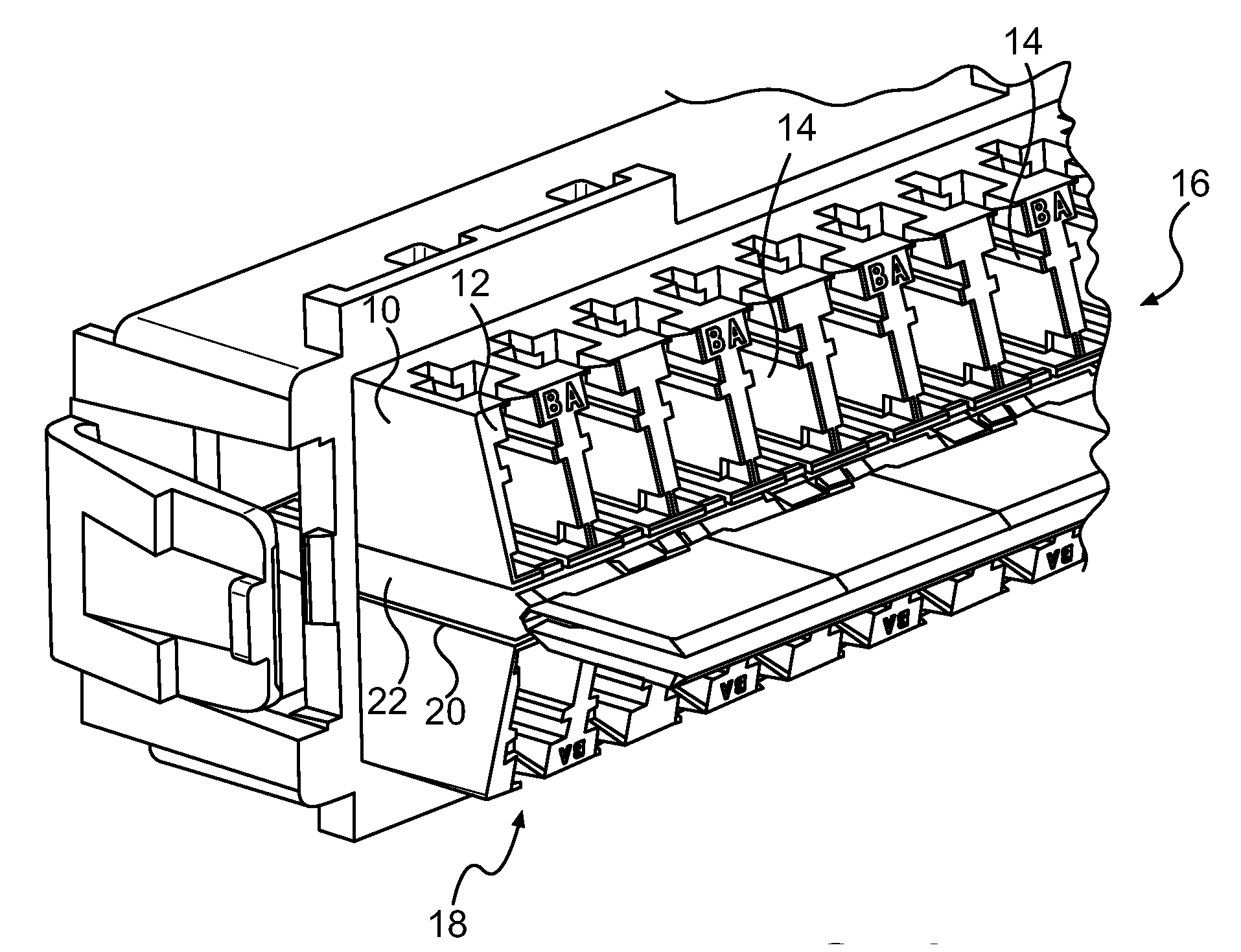
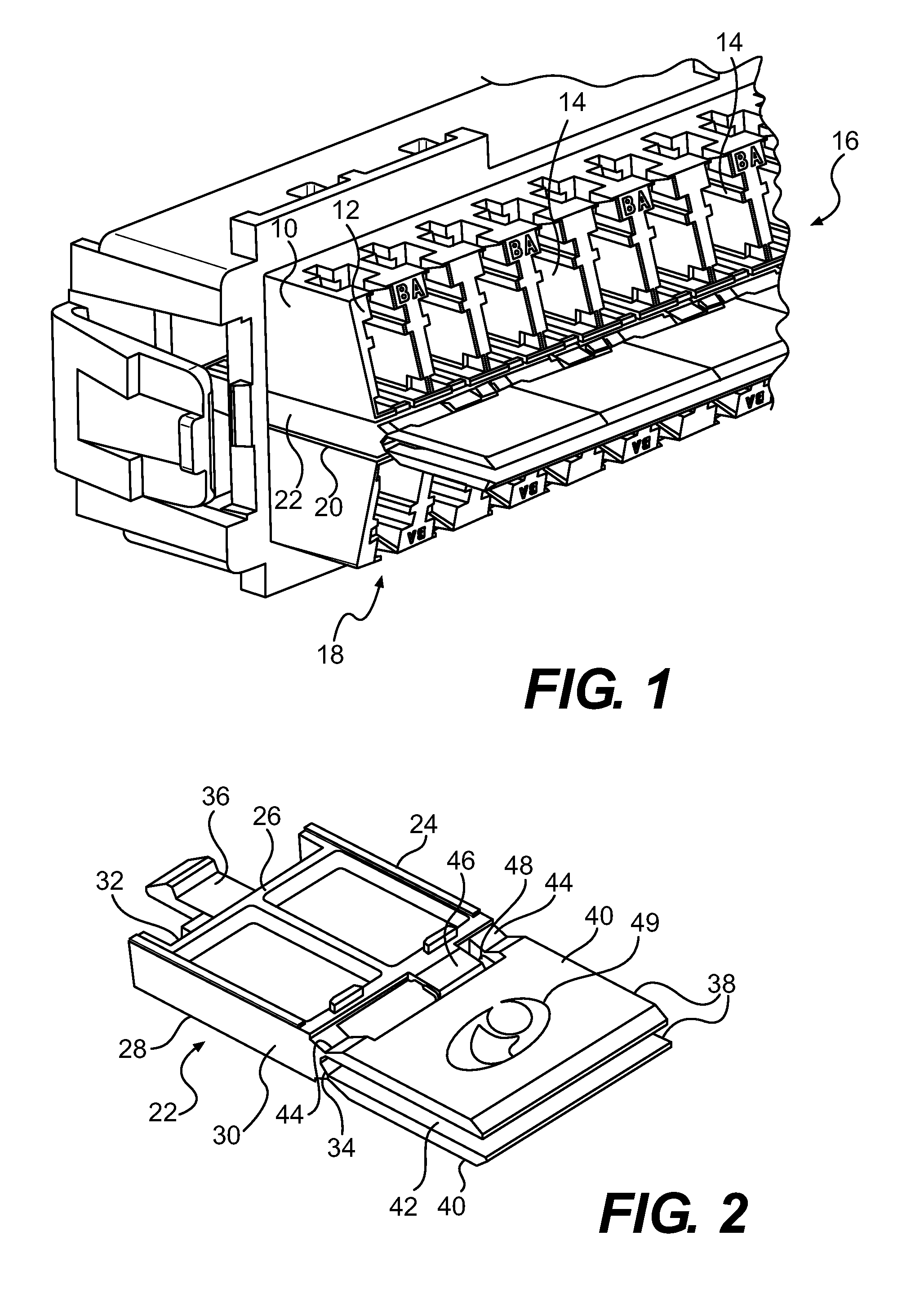
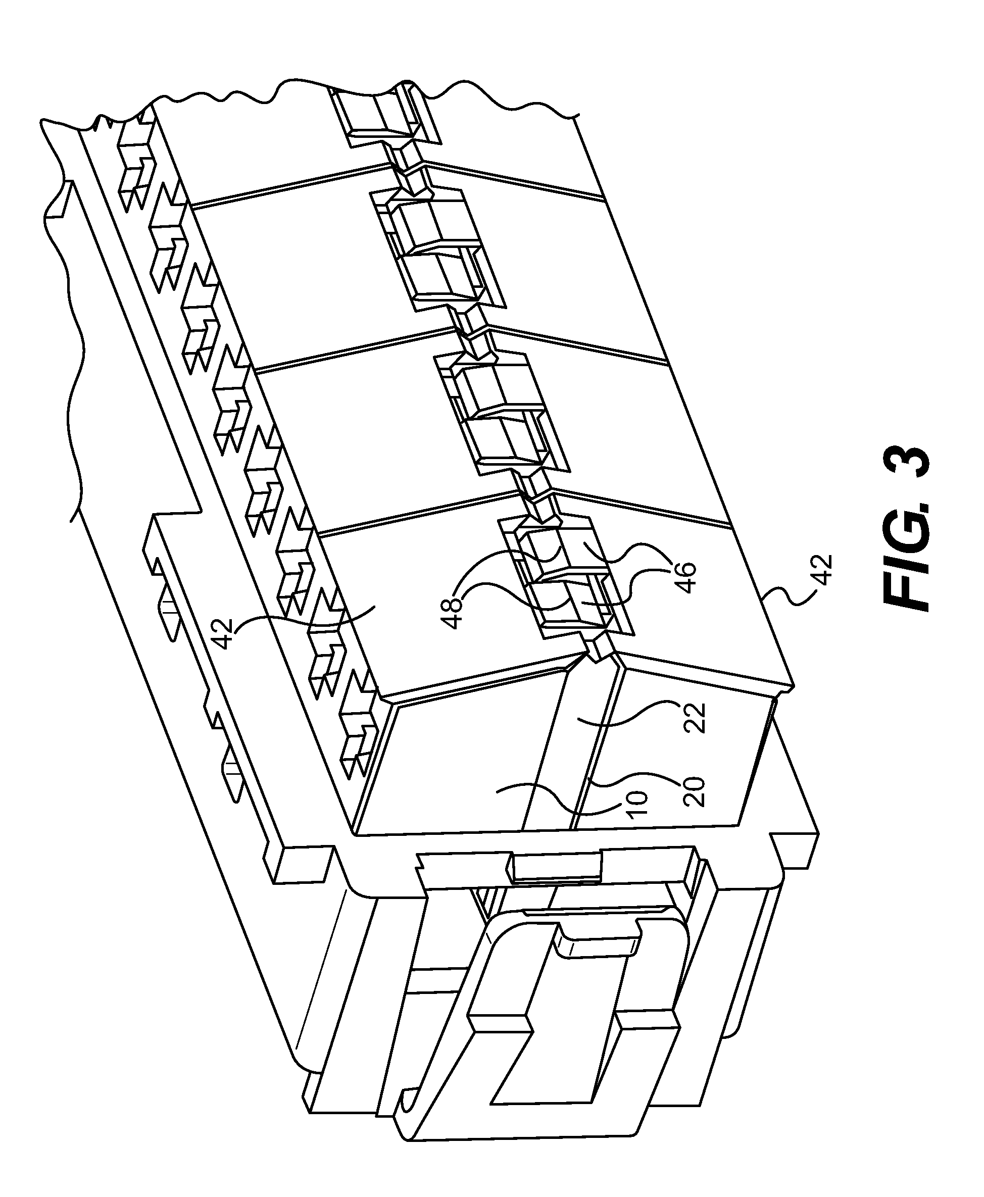
[0029]a shutter component 50 is illustrated in FIG. 4. Shutter component 50 includes a shutter base 52 that is configured to be received in an opening on a fiber optic adapter such as opening 20 in fiber optic adapter 10 of FIG. 1. Shutter base 52 has a front side 54 to which first and second shutters 56 having contacting faces 58 and exposed faces 60 are attached by a flexible hinge 62, and first and second side portions 64 on either side of front side 54. Each of the side portions 64 includes a reduced thickness portion 66 having a flexible, angled end portion 68 with a sliding surface 70. Each shutter 56 includes a tab 72 projecting from the shutter on one side of the flexible hinge 62 and having a sliding end 74 engaging the sliding surface 70 of one of the angled end portions 68.

[0030]The upper shutter 56 illustrated in FIG. 4 is biased toward a closed position in which contacting face 58 would be biased against the front wall 12 of fiber optic adapter 10 over one or more recep...

third embodiment

[0031]FIG. 5 illustrates a shutter component, shutter component 80. Shutter component 80 includes a shutter base 81 having a front wall 82 to which first and second shutters 84 are attached by first, second and third flexible hinge members 86 and one spring arm 88 connected between each shutter 84 and a pair of the first, second and third flexible hinge members 86. The length of spring arm 88 is selected such that it is slightly curved away from a relaxed, linear configuration when the shutter 82 is in a closed configuration (not illustrated but similar to the closed configuration of the upper shutter 56 of FIG. 4) and the open position illustrated in FIG. 5. To shift a shutter 84 between the first and second positions, the shutter 84 is moved by an operator toward the second position which movement increases the curvature of the spring arm 88 for the first portion of the shutter's travel. When the shutter 84 moves approximately half way toward the second position, the spring arm 88...


PUM


Abstract

A fiber optic component includes a body having at least one receptacle configured to receive a fiber optic connector, a shutter base mounted to the body at a mounting location adjacent to the at least one receptacle, and a first shutter connected to the shutter base by a first hinge. The first shutter, first hinge and shutter base are unitarily formed, and the first shutter is shiftable from a first position biased against the body and covering the at least one receptacle to a second position biased to an angularly spaced position relative to the first position.

Description

CROSS-REFERENCE TO RELATED APPLICATIONS[0001]The present application claims the benefit of U.S. Provisional Patent Application No. 61 / 233,544, filed Aug. 13, 2009, the entire contents of which is hereby incorporated by reference.FIELD OF THE INVENTION[0002]The present invention is directed to a shutter for selectively covering a receptacle of a fiber optic component and toward a fiber optic component including such a shutter, and, more specifically, toward a two-position shutter device for selectively covering one or more receptacles of a fiber optic component and toward a fiber optic component including such a shutter device.BACKGROUND OF THE INVENTION[0003]One type of fiber optic organization component, such as a fiber tray, shelf, rack or panel, receives a trunk cable made up of a plurality of optical fibers. These fibers are fanned out at the organization component and individually connected to a plurality of female receptacles. Male connectors can be plugged into the receptacle...

Claims


Application Information

Patent Timeline
IPC IPC(8): G02B6/36G02B6/00
CPCG02B6/3849G02B6/3825G02B6/3897
Inventor MUDD, RONALDLIVINGSTON, JOSEPHBILLMAN, BRADCRAIN, THOMASFAHD, ALYGIBBS, GARYNIELSON, JEFFREY DALERUIZ, GILWOMACK, WADE JAMES
Owner COMMSCOPE INC
Learn More