

Feeding system comprising parallel pumps for a continuous digester
- Summary
- Abstract
- Description
- Claims
- Application Information
AI Technical Summary
Benefits of technology
Problems solved by technology
Method used
Image

Examples
first embodiment
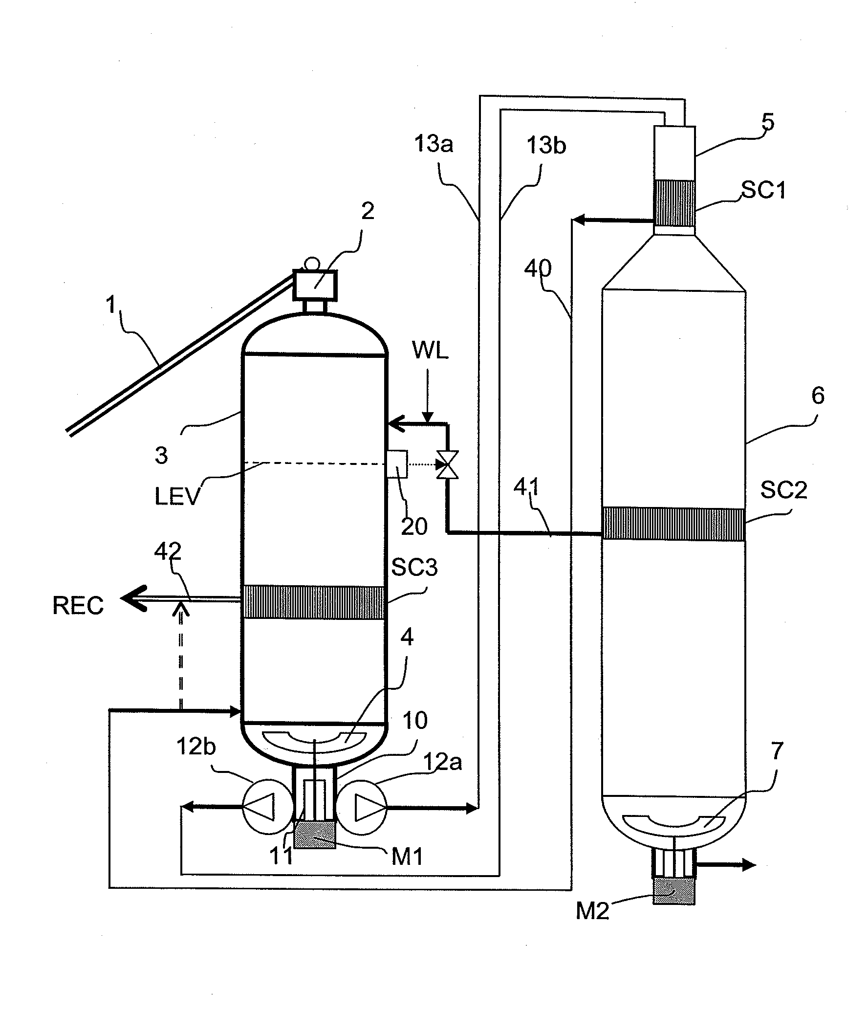
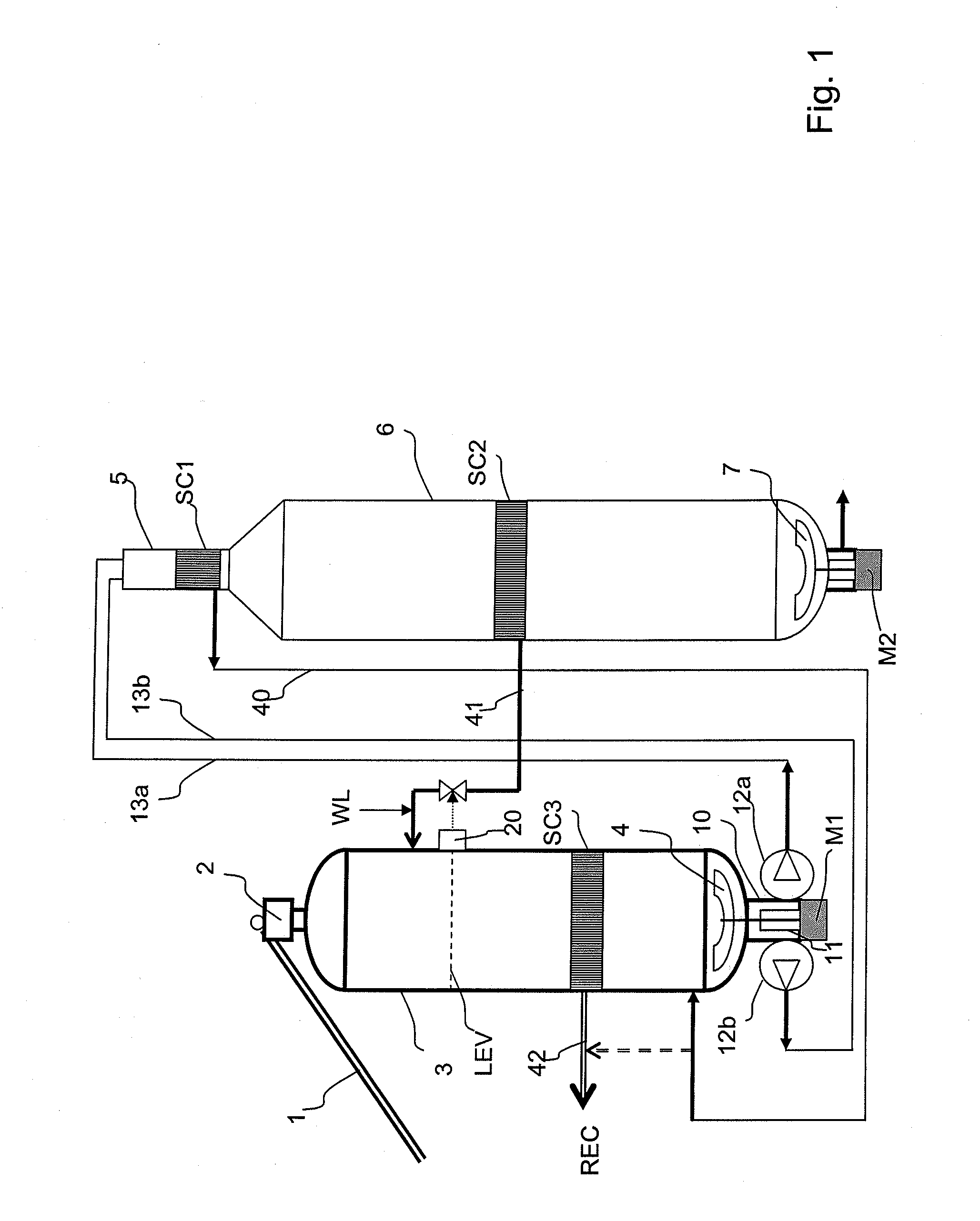
[0052]FIG. 1 shows an embodiment of the feed system with at least 2 pumps in parallel. The chips are fed with a conveyor belt 1 to a chips buffer 2 arranged on top of an atmospheric treatment vessel 3. In this vessel, a lowest liquid level, LIQLEV, is established by adding an alkali impregnation liquid, preferably cooking liquor (black liquor) that has been drawn off in a strainer screen SC2 in a subsequent digester 6, and with a possible addition of white liquor and / or another alkali filtrate.
[0053]The chips are fed with a normal control of the chip level CHLEV which is established above the liquid level LIQLEV.
[0054]The remaining alkali content in the black liquor is typically between 8-20 g / l. The amount of black liquor and other alkali liquids that are added to the treatment vessel 3 is regulated with a level transmitter 20 that controls at least one of the flow valves in lines 40 / 1. With this alkali impregnation liquor the wood acidity in the chips may be neutralised and impreg...
second embodiment
[0066]FIG. 8 shows an alternative embodiment for the feed system to a continuous digester without a top separator where each pump 12a, 12b pumps the chips suspension through a first section 13a, 13b of a transfer line to the top of the digester, and the first sections of the transfer lines from at least 2 pumps are combined at a merging point 16 to form a combined second section 13ab of the transfer line before this second section is led to wards the top of the digester. To maintain a constant flow rate, a supply line 15 is also connected to the merging point 16. In this embodiment black liquor is taken from line 41 and may be pressurised with a pump 14. However, because the black liquor has already reached a full digester pressure, the need to pressurise the liquor is limited.
[0067]All other characterizing parts of the system correspond to the system shown in FIG. 1.
[0068]FIG. 9 shows an example of how supply lines 15a, 15b that are used in the second embodiment may be connected to...
PUM
| Property | Measurement | Unit |
|---|---|---|
| Length | aaaaa | aaaaa |
| Volume | aaaaa | aaaaa |
| Mass | aaaaa | aaaaa |
Abstract
Description
Claims
Application Information