
Method and device for heating a fluid

Inactive Publication Date: 2011-01-13
ALU INNOVATION
View PDF1 Cites 3 Cited by
  • Summary
  • Abstract
  • Description
  • Claims
  • Application Information

AI Technical Summary

Benefits of technology

[0011]By this method it is possible to perform heating of different liquids, included melted materials and gases. The effect which is produced by the flame arc is controlled by regul

Problems solved by technology

This device cannot be used for heating liquids without electrical conductance, and does not give satisfactory possibility for control of the output.
An weakness related to this device

Method used


Image

  • Method and device for heating  a fluid
  • Method and device for heating  a fluid
  • Method and device for heating  a fluid

Examples


Example

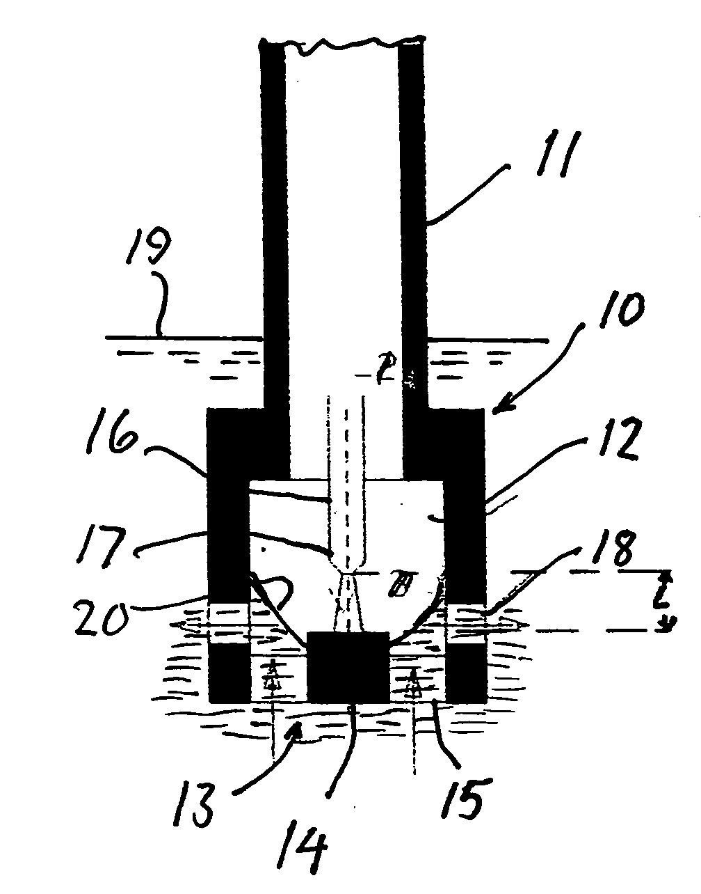
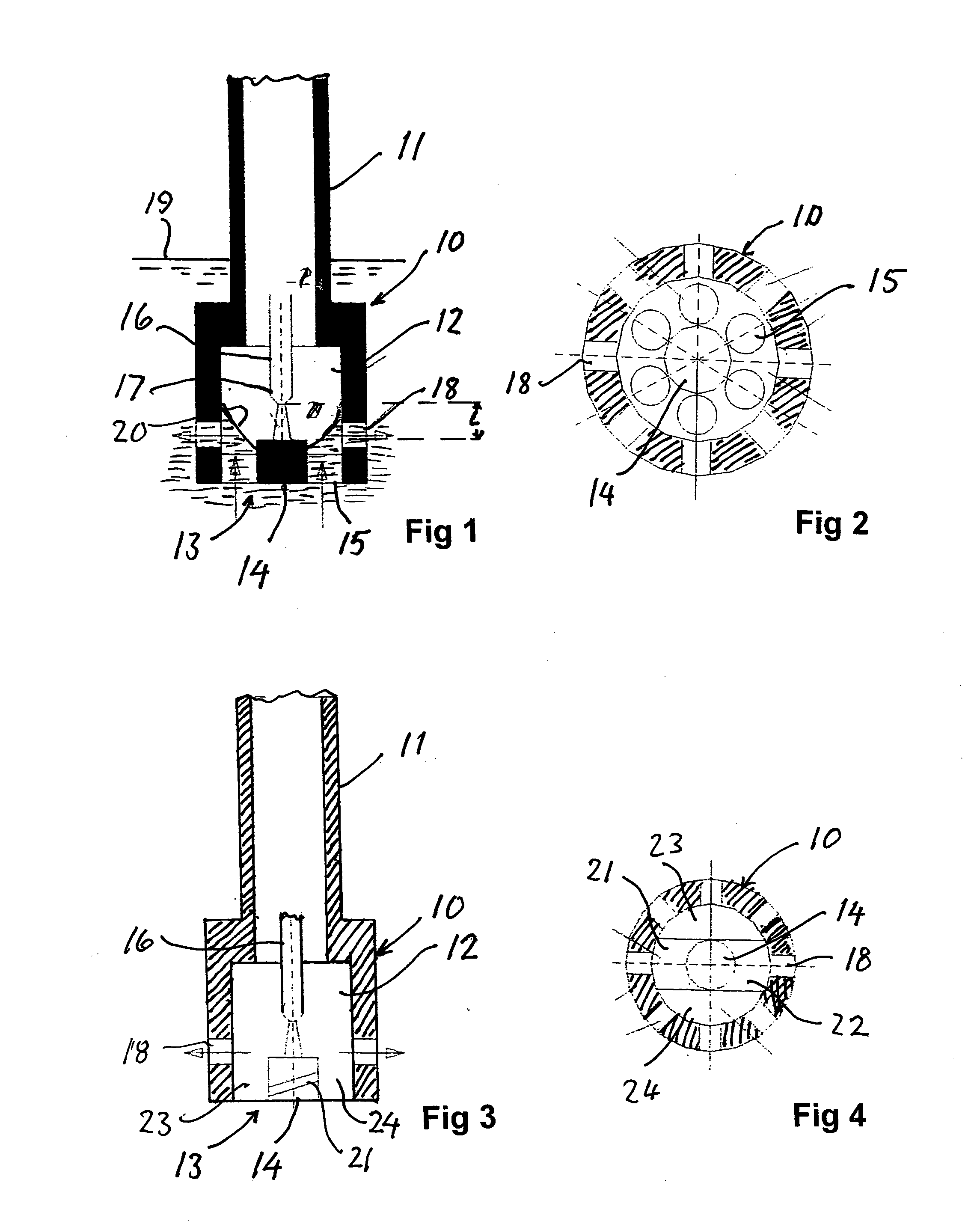
[0022]FIG. 1 shows a circle symmetric metallic rotor body 10 which is carried by a tubular shaft 11 with a common vertical axis. The shaft 11 is connected to a known drive gear and may be adapted for elevation and lowering relatively to a surrounding chamber (not shown). The shaft 11 is tubular for supply of gas, liquid and / or particles, to the chamber incorporating the rotor.

[0023]Thus the rotor body 10 is arranged to be arranged in a chamber, for example a melting furnace or hot water container. In the shown example the rotor body 10 has an inner consentric chamber 12 which is closed downwards with a bottom wall 13. The bottom wall 13 has a central hub electrode 14 which is surrounded by an annular series of axial holes 15, in the shown embodiment six holes, which are evenly distributed along the periphery.

[0024]The holes 15 may also have an oblique position, possibly also helical, to create a pumping effect during rotation.

[0025]In the rotor body 10 a centrally postioned electric...


PUM


Abstract

Method for heating a fluid, in particular a fluid which is not electrical conductive, where a rotor body (10) which is arranged in a chamber for absorption of the fluid, is rotated with a generally vertical shaft (11). A voltage is applied to a rod shaped electrode (16) which is arranged centrally in a rotor chamber (12) and to an electrode at the bottom (13) of the rotor chamber, for creation of a flame arc, so that a flow of the fluid passing the flame arc is created. The length (L) of the flame arc is held generally stable, preferably constant by controlling the position of the rod shaped electrode (16). The fluid is made enter the rotor chamber (12) so that it is kept outside the flame arc, and that the fluid is provided to flow through the rotor chamber (12).

Description

[0001]The invention relates to a method as described in the introductory part of claim 1, for heating a fluid by maintaining a flame arc in a rotor which is, at least partly, immersed in the fluid. Further it comprises a device as described in the introductory of claim 3, in order to carry out this method. “Fluid” is used to comprise all liquids, gases and particles and mixtures of these which may be pumped and transported to and from a container where the device is arranged.BACKGROUND [0002]From Norwegian patent 154498 it is known a device for heating liquid metal with a flame arc which is created between a fixed, axially positioned electrode and liquid metal. This device cannot be used for heating liquids without electrical conductance, and does not give satisfactory possibility for control of the output.[0003]From Norwegian patent 318848 it is known a device for heating liquid metal, where in a container with a cover with openings for delivery and removal of liquid metal a rotor ...

Claims


Application Information

Patent Timeline
IPC IPC(8): H05B7/18
CPCC22B4/005C22B4/08C22B9/05H05B7/22F27D11/10H05B7/18F27D11/08
Inventor VENAAS, KARL
Owner ALU INNOVATION
Learn More