Solar Heat Powered System comprising at least one solar collector

Inactive Publication Date: 2009-12-17
PAW
View PDF38 Cites 0 Cited by
  • Summary
  • Abstract
  • Description
  • Claims
  • Application Information

AI Technical Summary

Benefits of technology

[0012]Preferably, the heat exchangers are arranged in a vertical orientation of their media f

Problems solved by technology

Due to the increasing costs for primary energy, solar collector fields ar

Method used


Image

  • Solar Heat Powered System comprising at least one solar collector
  • Solar Heat Powered System comprising at least one solar collector
  • Solar Heat Powered System comprising at least one solar collector

Examples


Example

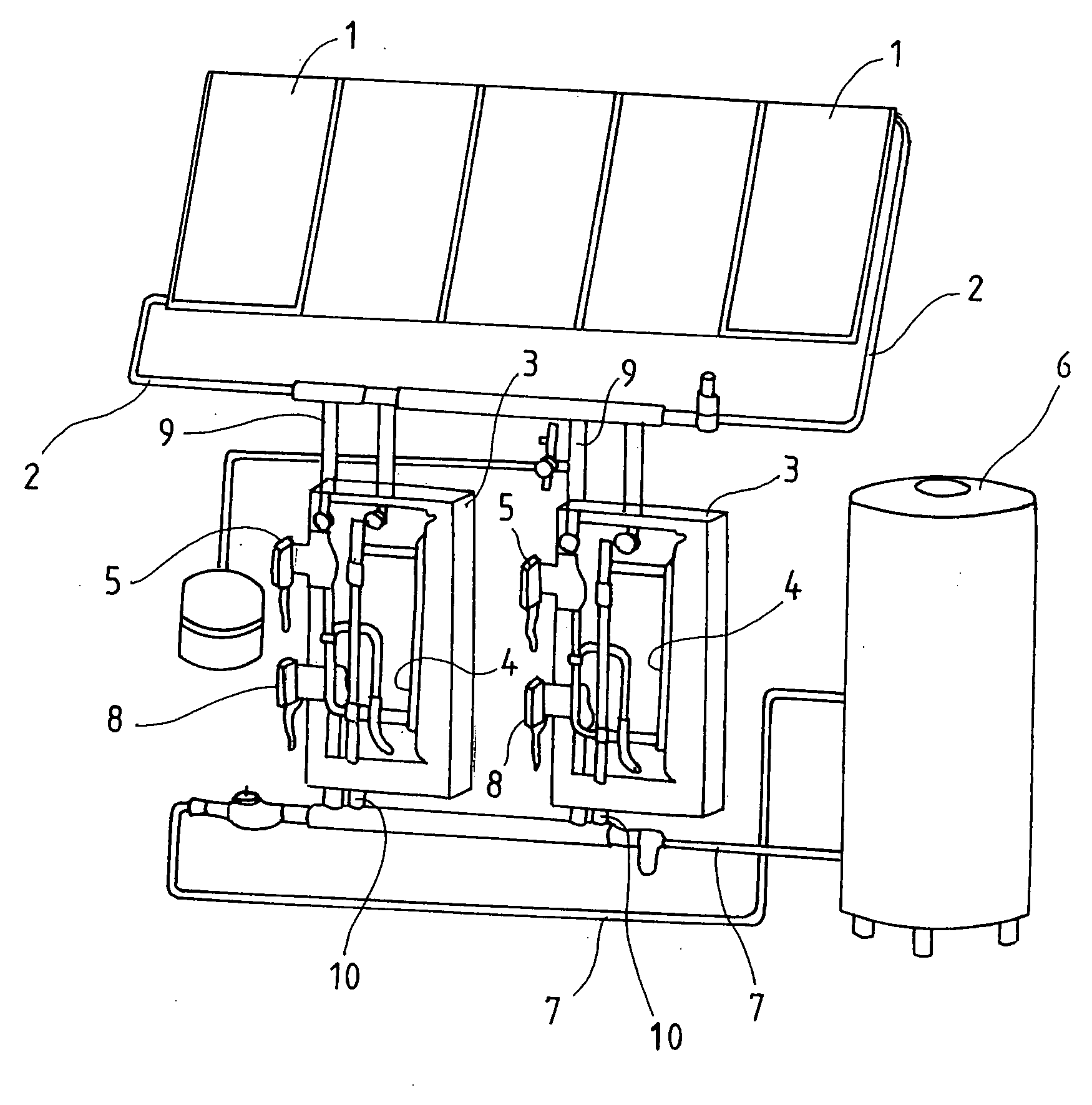
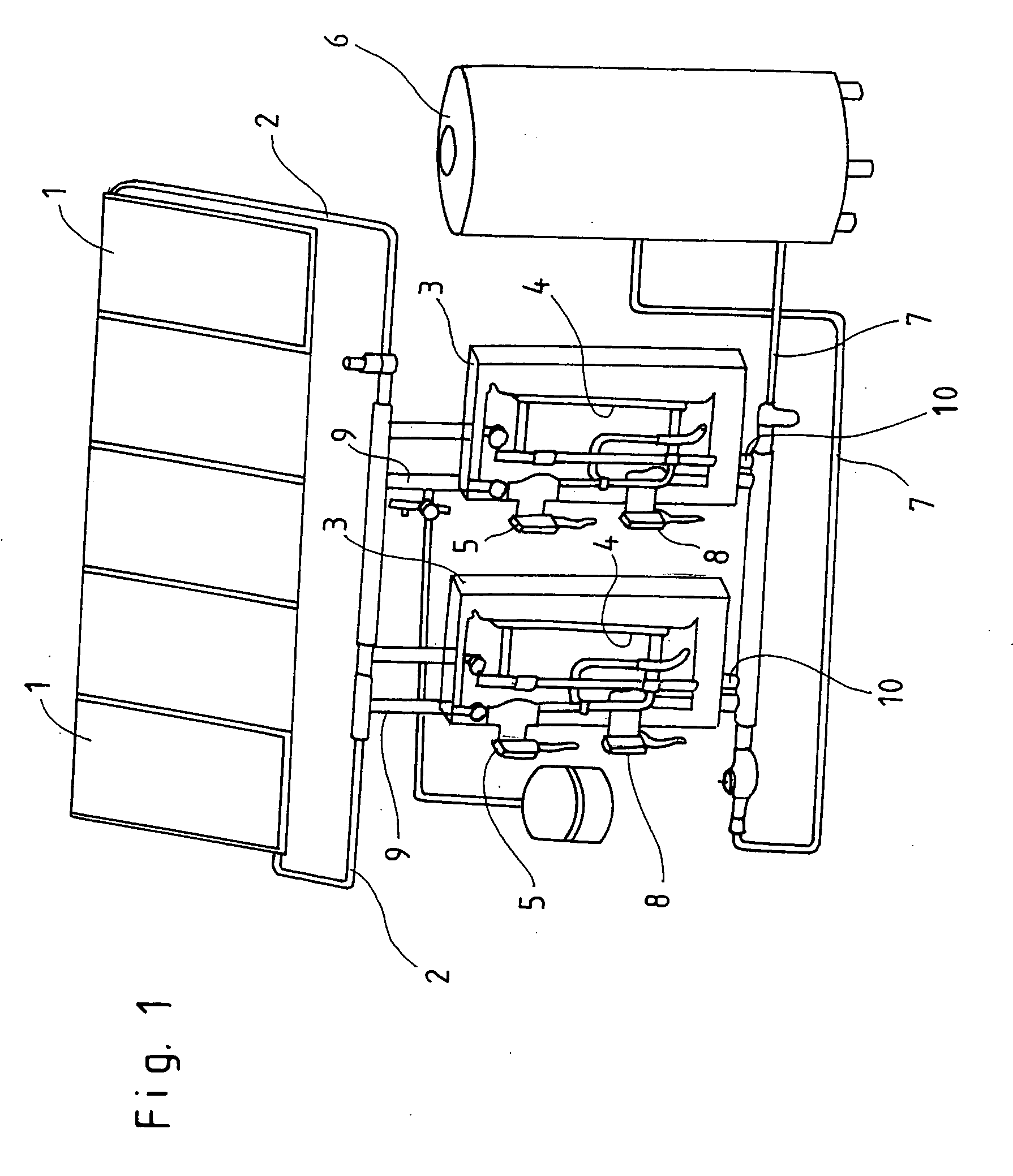
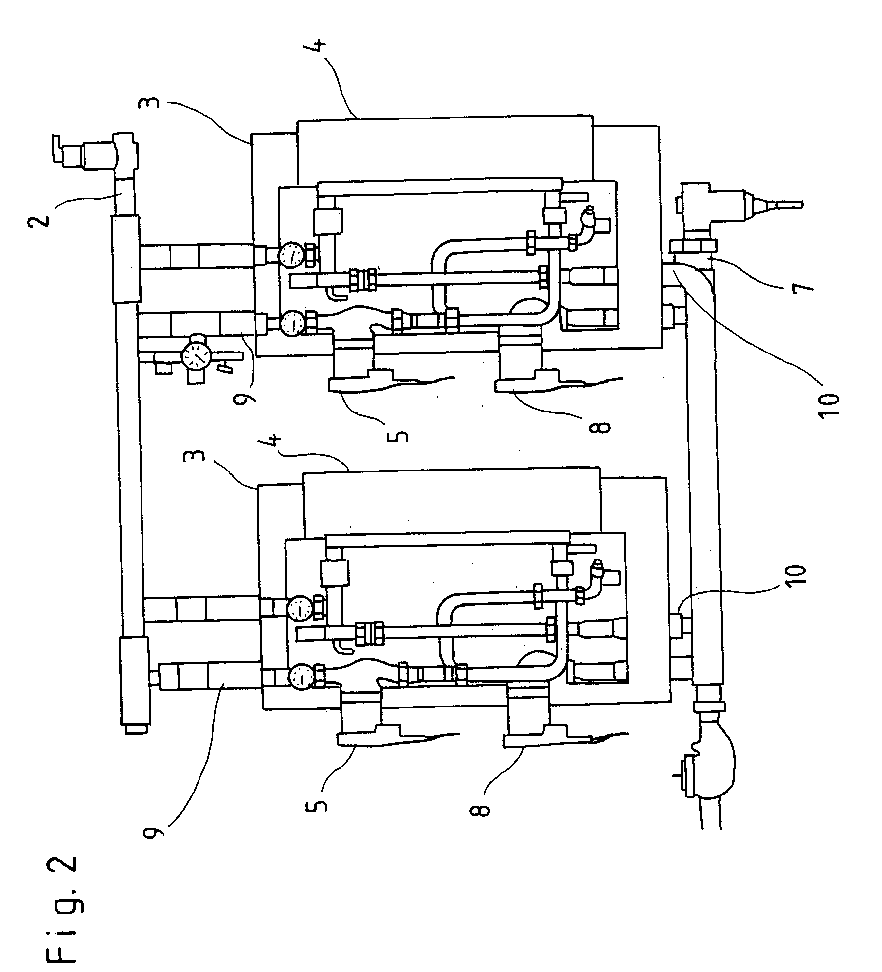
[0016]The solar heat powered system in FIG. 1 encompasses solar collectors 1, which are arranged on a roof, for example. A solar fluid is guided to heat transfer stations 3 via lines 2. A heat exchanger 4 is arranged in each heat transfer station 3. The solar fluid is conveyed by a pump 5; it flows through the heat exchanger 4 and back again to the solar collector 1 via the line 2.

[0017]The solar heat powered system furthermore encompasses an accumulator 6. A secondary heat carrier is guided out of this accumulator 6 to the heat transfer stations 3 via lines 7 and is likewise guided through the heat exchanger 4 by means of pumps 8.

[0018]Provision is made according to the invention for the line 2 from the solar collectors 1 to the heat exchangers 4 to be divided into two partial lines 9. Both heat exchangers 4 are arranged parallel to one another; standardized heat transfer stations 3 can be used thereby. The line 7 for the industrial water is necessarily also divided into partial li...


PUM


Abstract

A solar heat powered system has at least one solar collector and a feed line for solar fluid leading away from the solar collector. The feed line is divided into at least two partial lines in sections. There is at least one heat exchanger arranged in each partial line. By dividing the feed line for the solar fluid, the plurality of heat exchangers can each be embodied to be more compact.

Description

CROSS REFERENCE TO RELATED APPLICATIONS[0001]Applicants claim priority under 35 U.S.C. §119 of German Application No. 20 2008 007 796.6 filed Jun. 11, 2008.BACKGROUND OF THE INVENTION[0002]The invention relates to a solar heat powered system comprising at least one solar collector, to which lines for a solar fluid are connected[0003]Solar heat powered systems are used to heat secondary heat carriers (heating circuit water, potable water, cooling brine). A solar fluid is heated for this purpose in thermal solar collectors. The heated solar fluid is brought into operative heat-transferring connection with the secondary heat carrier via lines in heat exchangers so as to heat the secondary heat carrier.[0004]Due to the increasing costs for primary energy, solar collector fields are designed to be increasingly larger. Solar collector surfaces leading to a large volume of solar fluid, which is heated in midsummer, is available in particular for industrial users. To be able to process thes...

Claims


Application Information

Patent Timeline
IPC IPC(8): F24J2/04
CPCF24D11/003Y02B10/20F24D19/1042
Inventor VEHMEIER, JOERGHEINKE, MARTIN KARL
Owner PAW
Why Eureka
Try Eureka