

Touch device
- Summary
- Abstract
- Description
- Claims
- Application Information
AI Technical Summary
Benefits of technology
Problems solved by technology
Method used
Image

Examples
second embodiment
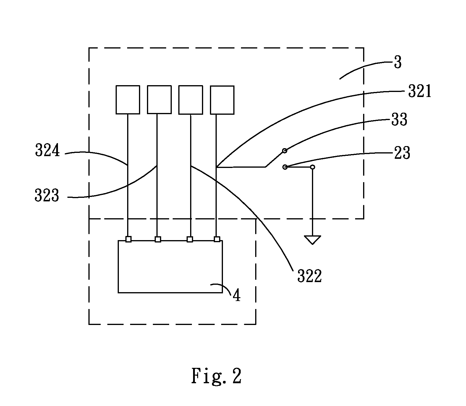
[0043]FIGS. 5, 6, and 7 show the present invention. The second conductor 33 and the first conductor 23 are arranged to be close to a middle line of the touch surface 31. Thus, not matter the conductive object 61 (such as the finger 61) presses the right portion of the touch surface 31 as shown in FIG. 6, or the conductive object 61 (such as the finger 61) presses the left portion of the touch surface 31 as shown in FIG. 7, the second conductor 33 can be electrically conducted with the first conductor 23. Although the control unit 4 only analyzes state of electrical conduction by means of the capacitive sensor 321 based on the above-mentioned two ways of pressing, the control unit 4 can still determine whether the electrical conduction is caused by pressing the right portion of the touch panel (FIG. 6) or by pressing the left portion of the touch panel (FIG. 7) based on the sensor signals of the other capacitive sensors 322, 333, 324. Thus, it is unnecessary to arrange two sets of co...
third embodiment
[0045]FIGS. 2 and 10 show the present invention. When a non-conductive object presses the touch surface 31 to electrically conduct the second conductor 33 with the first conductor 23, the control unit 4 determines the above state of electrical conduction based on the capacitive sensor 321, and determines no touch on the touch surface 31 so as to generate a third control signal. Different from the first control signal and the second control signal, the third signal may be, for example, a button switch signal, a signal indicative of number of pressing in duration, and a signal indicating pressing duration.
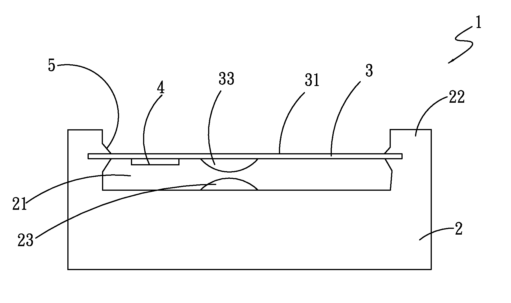
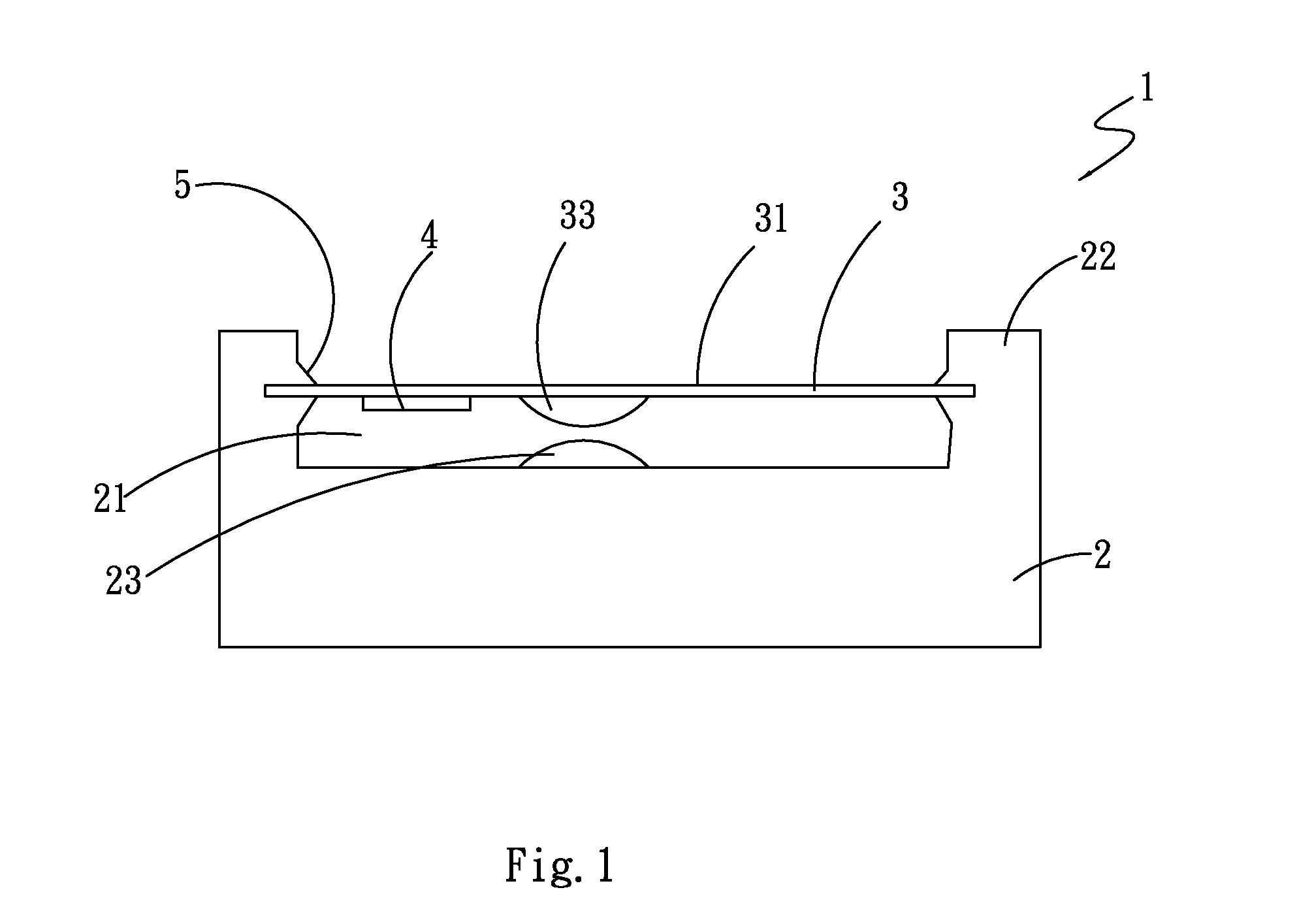
[0046]Please refer to FIGS. 3, 11 and 12 again. The base 2 has an accommodating region 21, at least one side wall 22, and a first conductor 23. The side wall 22 has a position recovering means 5 that is made of rubber or other polymeric materials of an elastic construction. In addition to make the touch surface 31 to suspend in one plane over the accommodating region 21 for relative ...
PUM
 Abstract
Description
Claims
Application Information