

Lighting unit for vehicles and mounting method
- Summary
- Abstract
- Description
- Claims
- Application Information
AI Technical Summary
Benefits of technology
Problems solved by technology
Method used
Image

Examples
Embodiment Construction
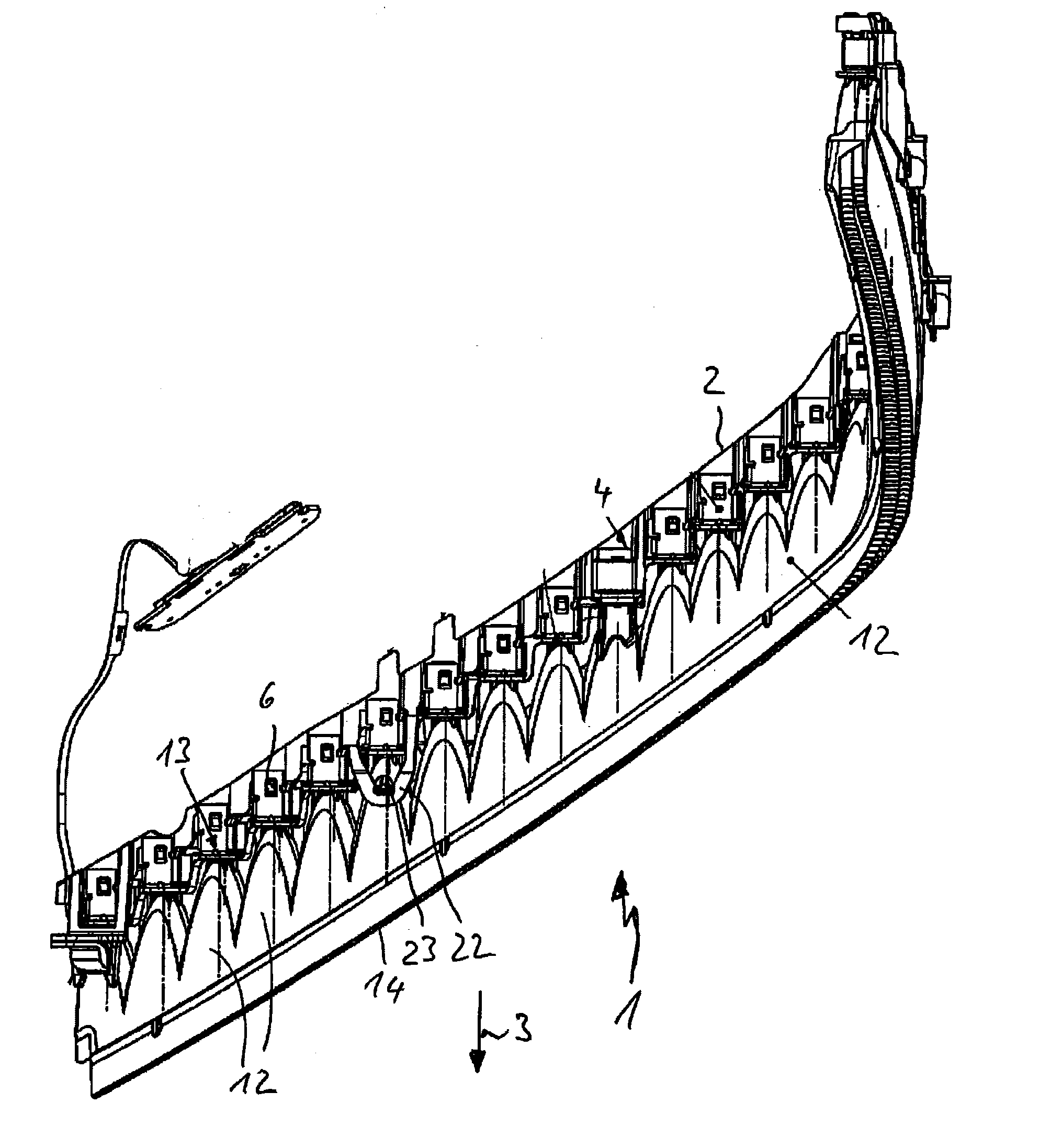
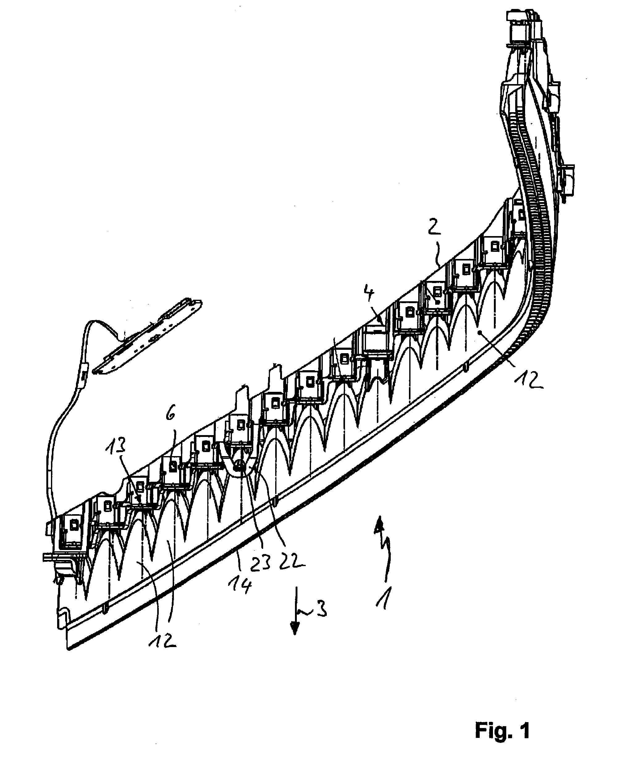
[0026]A lighting unit 1 for vehicles may, for example, generate a low beam, daytime running light, indicator light, position light function and / or a combination of these lighting functions and is installed at the front of a motor vehicle. The lighting unit 1 can be elongated and integrated in a headlamp of the vehicle.
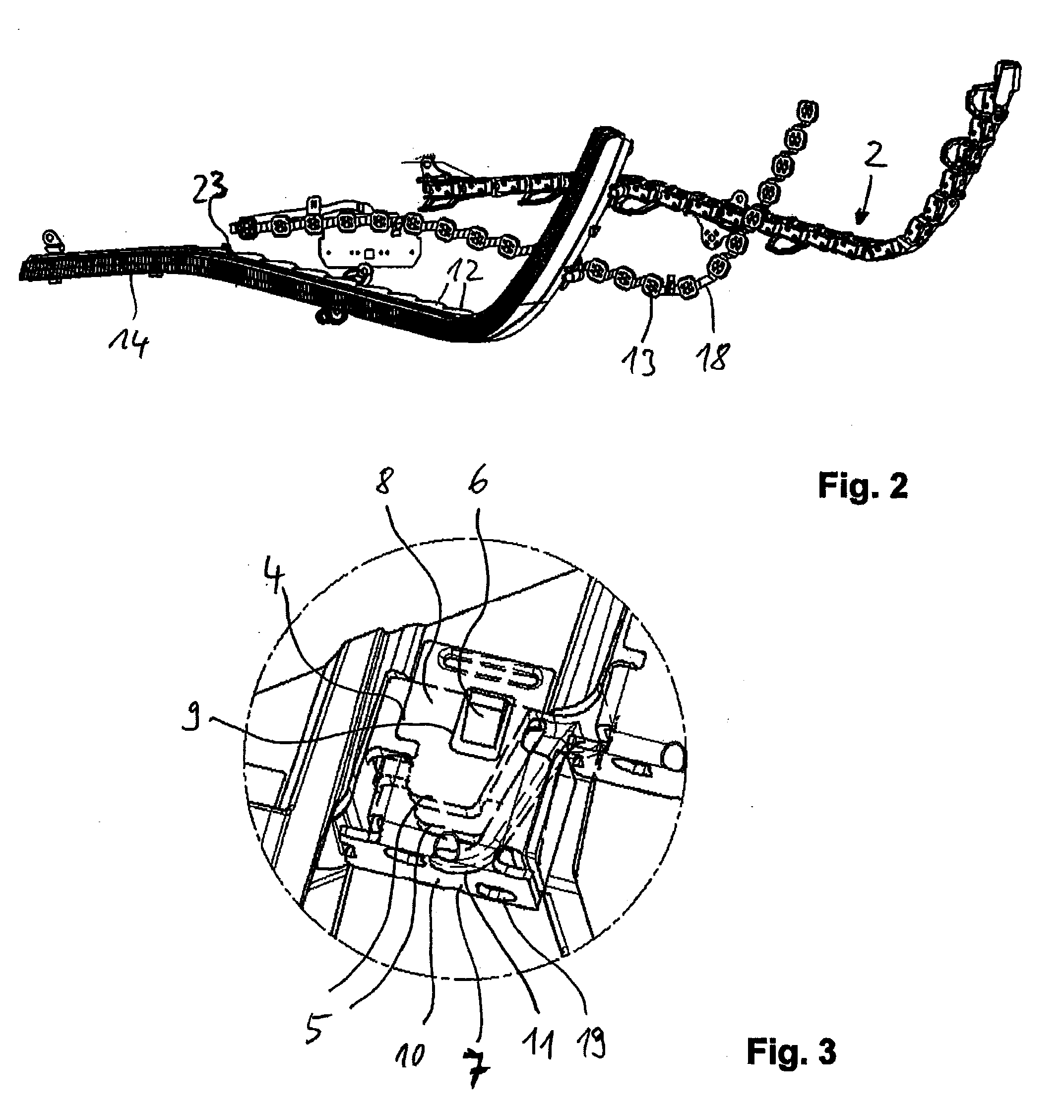
[0027]In the depicted embodiment, the lighting unit 1 comprises an elongated carrier frame 2 with a U-shaped cross-section such that said carrier frame 2 is mounted on a housing (not shown) of the headlamp. A plurality of rows of holding bodies 4 in a two-dimensional and three-dimensional arrangement are molded to a front side of the carrier frame 2 such that said front side is facing in the direction of light emission. Each holding body 4 is pot-shaped and comprises wall 5 protruding in the direction of light emission, wherein a top and / or a bottom wall 5 has a slanting face 6 narrowing in the direction of light emission 3 and serving as a locating element. The purpos...
PUM
 Abstract
Description
Claims
Application Information