
Lighting unit for vehicles and mounting method

a technology for vehicles and mounting methods, applied in fixed installation, lighting and heating apparatus, lighting support devices, etc., can solve problems such as unmounted units, and achieve the effect of accurate positioning and mounting, simple and cost-efficien

Active Publication Date: 2013-08-20
HELLA KG HUECK & CO
View PDF3 Cites 0 Cited by
  • Summary
  • Abstract
  • Description
  • Claims
  • Application Information

AI Technical Summary

Benefits of technology

[0005]The present invention presents a lighting unit for vehicle and a method of installing said lighting unit such that the components can accurately positioned and mounted in a simple and cost-efficient manner.

Problems solved by technology

A disadvantage of the prior art lighting unit is that the unit is not mounted until an extra step of the process is taken after slotting the holding turrets into the recesses.

Method used


Image

  • Lighting unit for vehicles and mounting method
  • Lighting unit for vehicles and mounting method
  • Lighting unit for vehicles and mounting method

Examples


Embodiment Construction

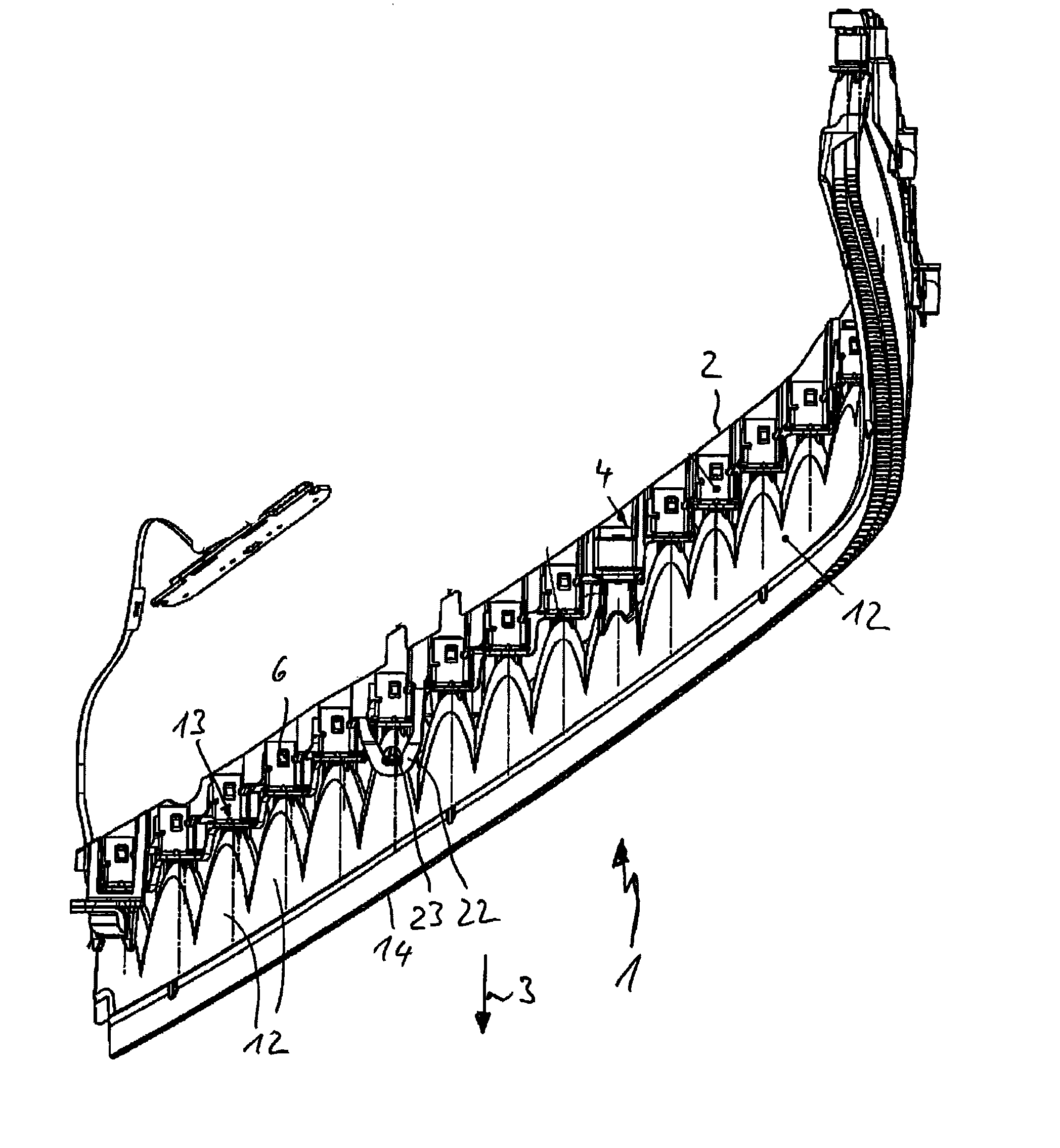
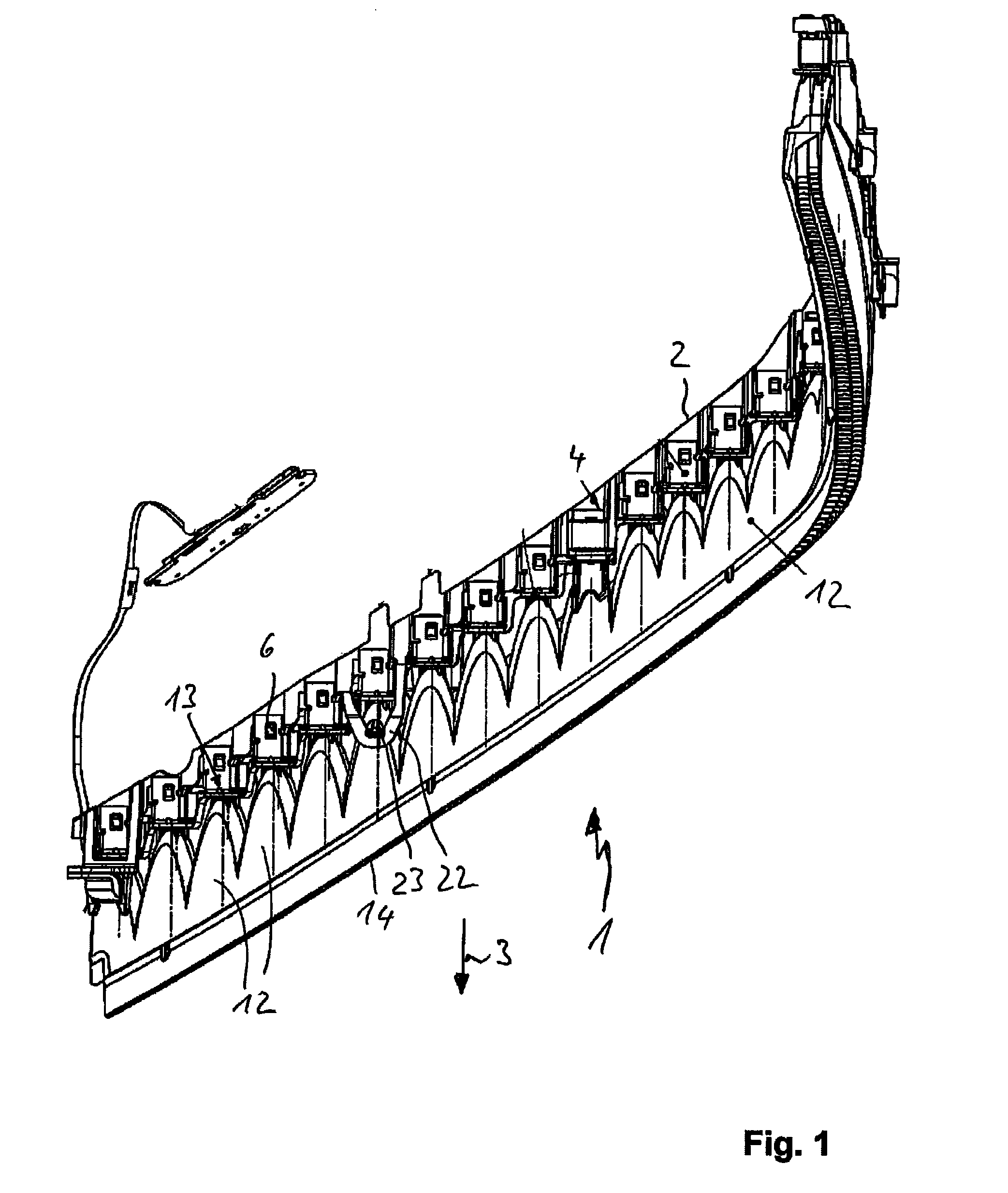
[0026]A lighting unit 1 for vehicles may, for example, generate a low beam, daytime running light, indicator light, position light function and / or a combination of these lighting functions and is installed at the front of a motor vehicle. The lighting unit 1 can be elongated and integrated in a headlamp of the vehicle.

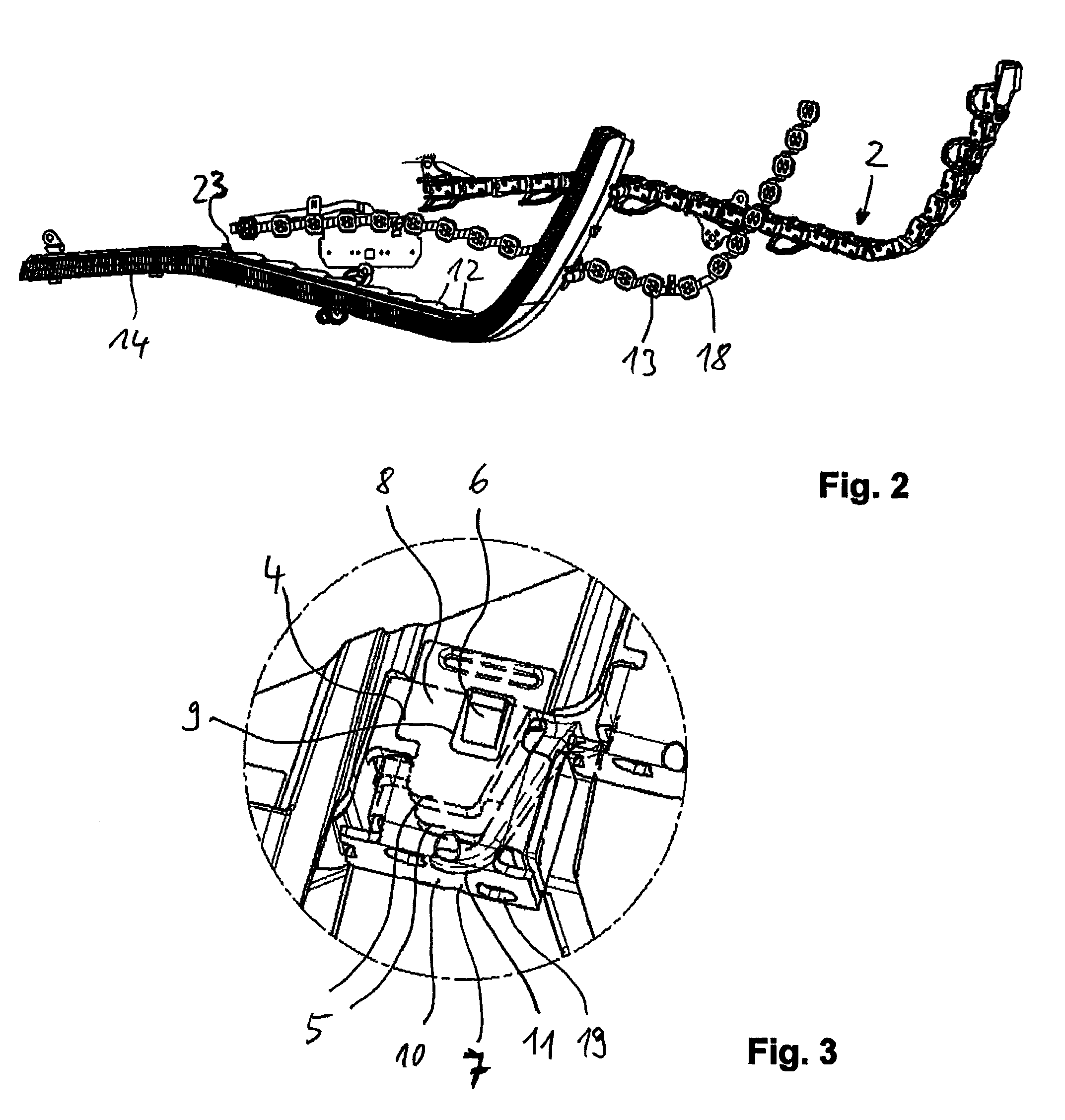
[0027]In the depicted embodiment, the lighting unit 1 comprises an elongated carrier frame 2 with a U-shaped cross-section such that said carrier frame 2 is mounted on a housing (not shown) of the headlamp. A plurality of rows of holding bodies 4 in a two-dimensional and three-dimensional arrangement are molded to a front side of the carrier frame 2 such that said front side is facing in the direction of light emission. Each holding body 4 is pot-shaped and comprises wall 5 protruding in the direction of light emission, wherein a top and / or a bottom wall 5 has a slanting face 6 narrowing in the direction of light emission 3 and serving as a locating element. The purpos...


PUM


Abstract

The present invention relates to a lighting unit for vehicles, comprising a light source arranged on a circuit board and further comprising an optical attachment mounted in the direction of light emission in front of the light source, said optical attachment comprising at least one holding turret on one of the sides facing the circuit board such that, at its mounting position, the holding turret slots into a hole drilled into the circuit board, wherein the optical attachment is positive-locking to a holding body arranged on one of the sides facing away from the light source, wherein the holding body is molded to a carrier frame, and wherein the holding body or the carrier frame snaps on to the optical attachment.

Description

CROSS-REFERENCE TO RELATED APPLICATIONS[0001]The present application claims priority to and incorporates herein by reference European Patent Application Serial No. 09 177 001.6 filed on Nov. 25, 2009.BACKGROUND[0002]The present invention relates to a lighting unit for vehicles, comprising a light source mounted on a circuit board and further comprising an optical attachment mounted in the direction of light emission in front of the light source, said optical attachment comprising at least one holding turret on one of the sides facing the circuit board such that, at its mounting position, the holding turret slots into a hole drilled into the circuit board, wherein the optical attachment is positive-locking to a holding body arranged on one of the sides facing away from the light source.[0003]The present invention further relates to a method of mounting a lighting unit such that an optical attachment is joined to a circuit board populated with multiple light sources and also joined to...

Claims


Application Information

Patent Timeline
Patent Type & Authority Patents(United States)
IPC IPC(8): F21V11/00
CPCF21S48/1104F21S48/1208F21V17/164F21S48/211F21Y2101/02F21Y2115/10F21S41/19F21S41/29F21S43/19
Inventor SPORK, HEINZ-UWEMARTINEZ, SONIAHANUSCHKIEWITZ, DAVID
Owner HELLA KG HUECK & CO
Learn More