Vacuum cleaner nozzle for floors and carpets

a vacuum cleaner and nozzle technology, applied in the direction of vacuum cleaners, cleaning equipment, domestic applications, etc., can solve the problems of limited cleaning effect, comparatively high effort required for production of such vacuum cleaner nozzles, etc., and achieve good sealing effect, simple and therefore cost-effective construction, and good cleaning effect of the vacuum cleaner nozzle

Active Publication Date: 2007-08-07
WESSEL WERK
View PDF6 Cites 9 Cited by
  • Summary
  • Abstract
  • Description
  • Claims
  • Application Information

AI Technical Summary

Benefits of technology

[0006]It is therefore an object of the invention to provide a simple and cost-efficient vacuum cleaner nozzle for floors and carpets that cleans floors as efficiently as it does carpets.
[0011]The rocker allows a simple and therefore cost-efficient construction of the nozzle. The gasket elements arranged in front of and behind the suction port in the working direction achieve a very good sealing effect during the vacuuming of floors, thus ensuring a good cleaning effect of the vacuum cleaner nozzle on smooth floors as well.
[0012]In a preferred embodiment of the invention, the rocker is comprised of a pin-jointed frame plastic molding having a rod with cylindrical bearing surfaces and parallel profile strips to fasten the gasket elements, as well as cross-members that connect the rod and the profile strips. The cross-members are arranged on both sides of a suction channel that runs in the inside of the housing to an opening in the suction port. This allows a simple and cost-efficient production of the rocker, for example as a one-piece injection-molded part. Preferably, the rocker is guided on pivots that extend from the slide sole to the upper part of the housing and brace the housing. The rocker is loaded by at least one return spring, which can be developed as a torsion spring or a coil spring. Preferably, it is supported on coil springs that-are arranged on the pivots. This further simplifies the construction of the vacuum cleaner nozzle and provides the rocker with a very high functionality, in particular when moving out and retracting the gasket elements.
[0013]The rocker may have two respective cross-members on each side of the suction channel, with the actuating lever dipping into the free space between adjacent cross-members and with contact surfaces that also cooperate with the actuating lever being arranged between the cross-members. Despite the simple construction of the rocker, this lends the rocker a high stability and thus load capacity, and it furthermore enables a compact structure of the nozzle. The actuating lever is preferably comprised of a pivoted shaft, at least one actuating surface developed as an impact switch, and formed cam lobes, with the cam lobes acting on an assigned contact surface of the rocker. Then the actuating lever can be produced in a simple and cost-efficient manner, for example also as a one-piece injection-molded part. The construction described above guarantees a simple and therefore safe cooperation of actuating lever and rocker.

Problems solved by technology

The production of such vacuum cleaner nozzles requires a comparatively high effort.
However, the sealing function of the individual bristle strip and thus the cleaning effect when vacuuming of the floor, is limited.

Method used


Image

  • Vacuum cleaner nozzle for floors and carpets
  • Vacuum cleaner nozzle for floors and carpets
  • Vacuum cleaner nozzle for floors and carpets

Examples


Embodiment Construction

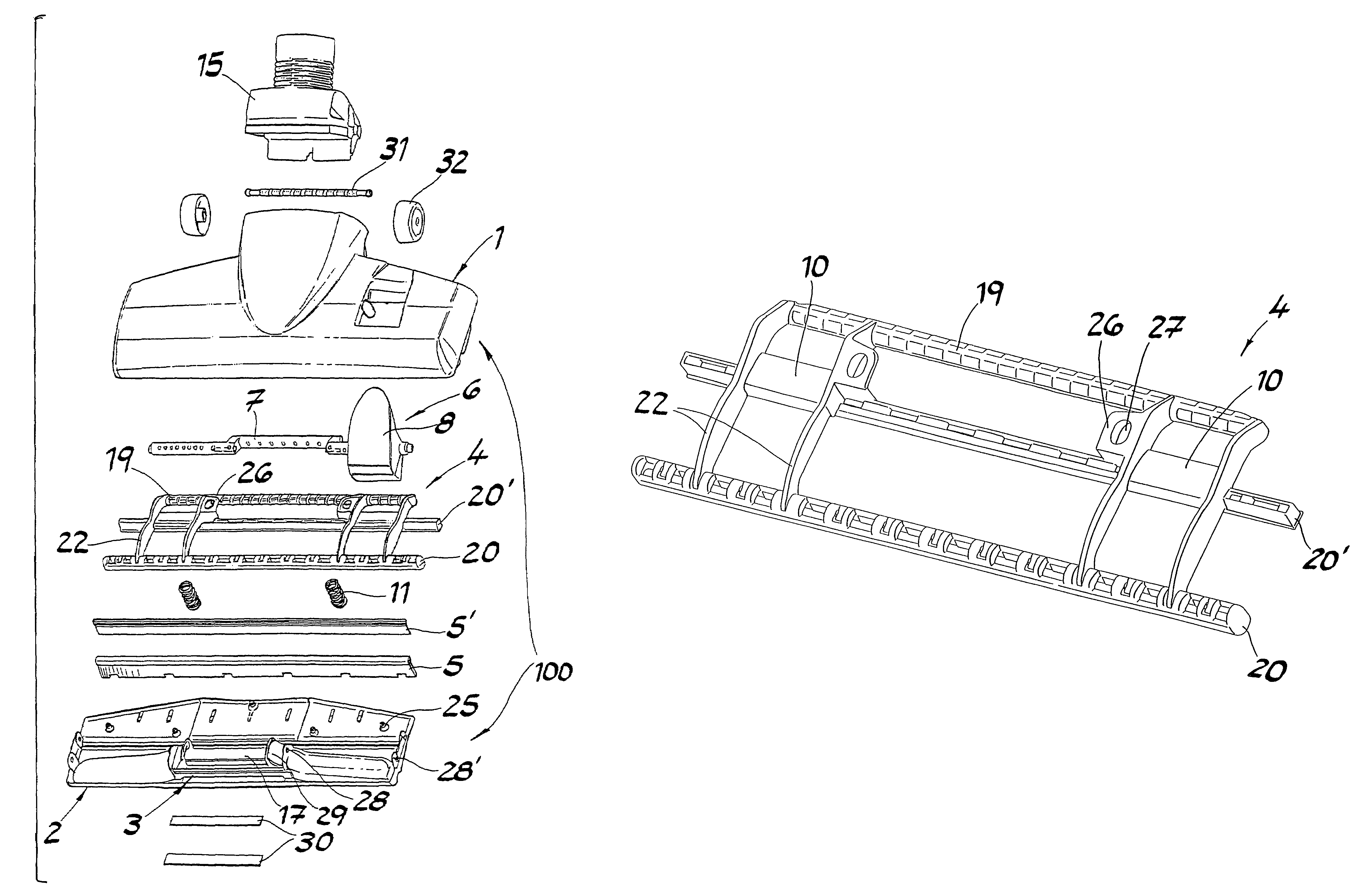
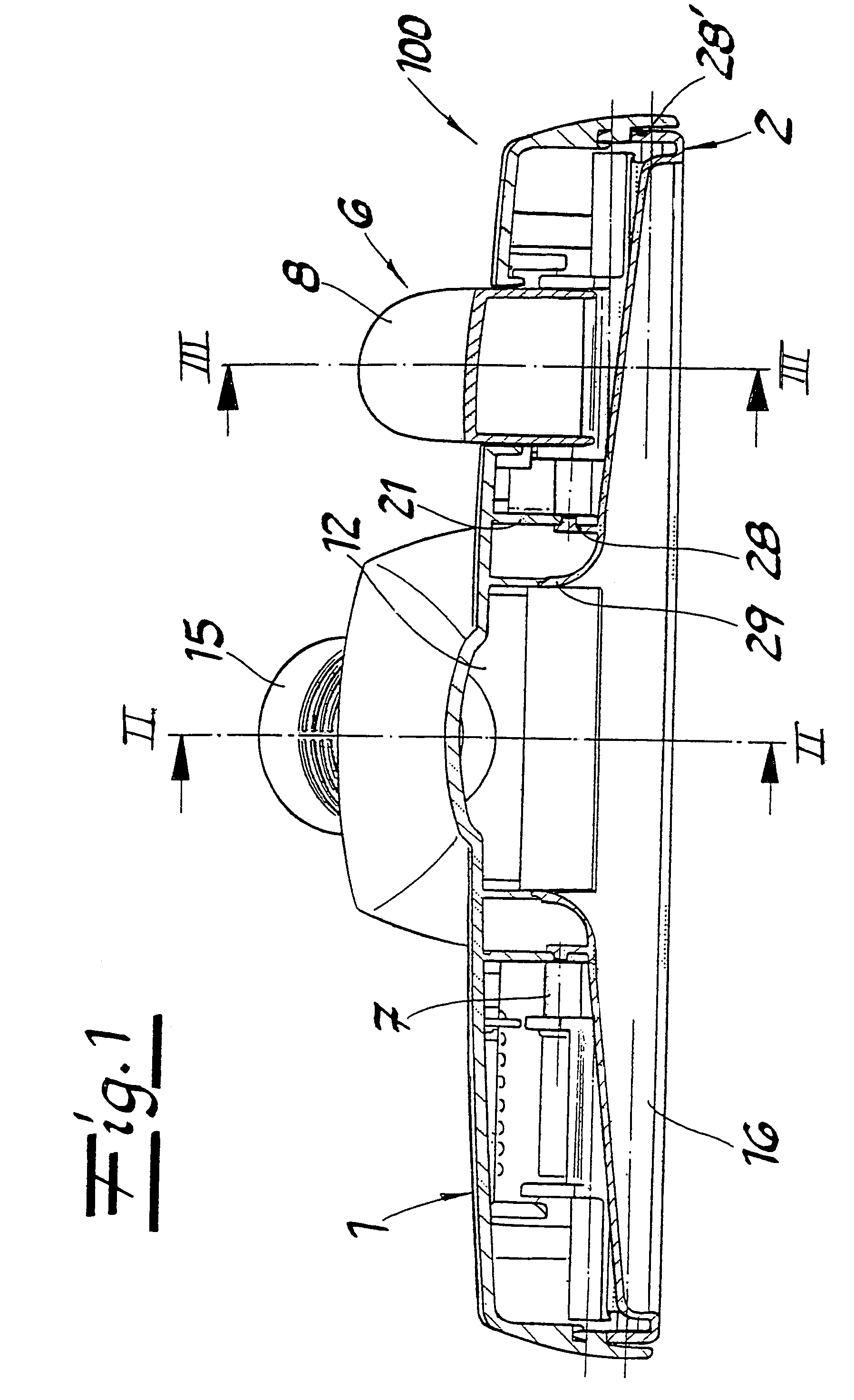
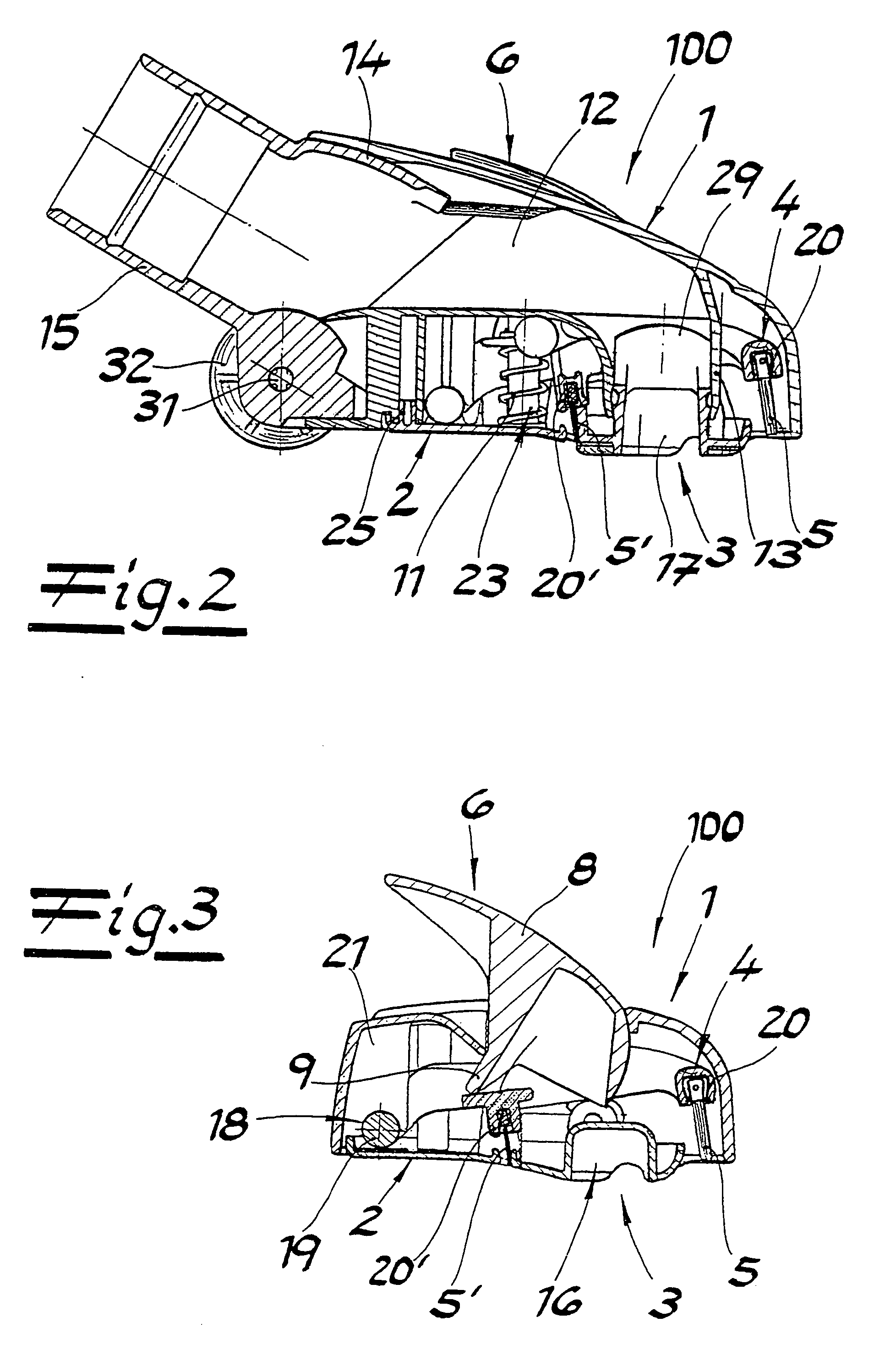
[0024]The vacuum cleaner nozzle shown in the figures can be used for floors and carpets either directly or with the interconnection of a flexible line on the suction side of a vacuum cleaner device. The principal structure of the vacuum cleaner nozzle includes a housing 100 with an upper housing part 1 made of plastic and a plastic slide sole 2 having a suction port 3 as well as a rocker 4 adjustably arranged inside upper housing part 1 with strip-shaped gasket elements 5, 5′ arranged in working direction in front of and behind suction port 3. Gasket elements 5, 5′ can be moved in and out of the openings at the lower side of housing 100 with a swing movement of rocker 4. The nozzle includes an actuating lever 6 comprised of a pivotable shaft 7, at least one actuating surface developed as an impact switch 8 as well as formed cam lobes 9 that act on a respective contact surface 10 of rocker 4. There are return springs 11 acting on rocker 4. A suction channel 12 is formed on upper part...


PUM


Abstract

A vacuum cleaner nozzle for floors and carpets having a housing comprised of an upper part and a slide sole, a pivotable rocker located in the housing on a rear segment in working direction and an actuating lever to operate the rocker. Strip-shaped gasket elements are attached to the rocker, which are arranged in working direction in front of and behind a suction port formed into the slide sole and can be retracted and moved out of openings on the lower side of the housing with a pivoting movement of the rocker.

Description

BACKGROUND OF THE INVENTION[0001]1. Field of the Invention[0002]The invention relates to a vacuum cleaner nozzle for floors and carpets.[0003]2. The Prior Art[0004]Vacuum cleaner nozzles with gasket elements that can be developed as bristle strips or elastomer strips are known. When vacuuming carpets, the gasket elements are retracted in the interior of the housing and the slide sole rests on the floor covering. To vacuum smooth floors, the gasket elements are moved out with an adjustment movement of the gasket base at the lower side of the nozzle, and support the upper part of the housing on the floor. The gasket base is often developed as a metal plate that is arranged to be vertically adjustable in the upper part of the housing and can be lowered against the action of return springs by means of a tilting lever that acts on the base plate, such as shown in German Patent No. DE 196 28 070 A1. The production of such vacuum cleaner nozzles requires a comparatively high effort.[0005]G...

Claims


Application Information

Patent Timeline
Patent Type & Authority Patents(United States)
IPC IPC(8): A47L9/06
CPCA47L9/06A47L9/0653
Inventor KAFFENBERGER, DIETERLIND, THOMAS
Owner WESSEL WERK
Why Eureka
Try Eureka