Electric machine and method of making an electric machine

a technology of electric machines and motors, applied in the field of electric machines, can solve the problems of increasing the loss of motors, cumbersome winding operation, and reducing the power density of motors, and achieve the effect of enhancing the stability of the stator

Inactive Publication Date: 2006-08-01
SIEMENS AG
View PDF7 Cites 9 Cited by
  • Summary
  • Abstract
  • Description
  • Claims
  • Application Information

AI Technical Summary

Benefits of technology

[0012]The stability of the stator can be enhanced by configuring the free ends of the comb teeth in a pointed manner for placement in complementary grooves of the core element during assembly. Suitably, the pointed free ends of the comb teeth lock into the grooves.

Problems solved by technology

In the event, it is desired to fill the slot with winding as much as possible, the winding operation become cumbersome because the stator winding must be wound through the narrow openings.
Using a needle arrangement to wind a copper coil results only in a limited slot filling degree so that the power density in the motor is decreased.
The draw-in technique requires a prolongation of the winding end portion so that the coil exhibits a higher electrical resistance, accompanied by greater losses in the motor.
The manual guiding-in technique is labor-intensive and thus expensive.
Thus, the winding quality becomes substandard, when the winding operation is carried out automatically.

Method used


Image

  • Electric machine and method of making an electric machine
  • Electric machine and method of making an electric machine

Examples


Embodiment Construction

[0020]Throughout all the Figures, same or corresponding elements are generally indicated by same reference numerals. These depicted embodiments are to be understood as illustrative of the invention and not as limiting in any way. It should also be understood that the drawings are not necessarily to scale and that the embodiments are sometimes illustrated by graphic symbols, phantom lines, diagrammatic representations and fragmentary views. In certain instances, details which are not necessary for an understanding of the present invention or which render other details difficult to perceive may have been omitted.

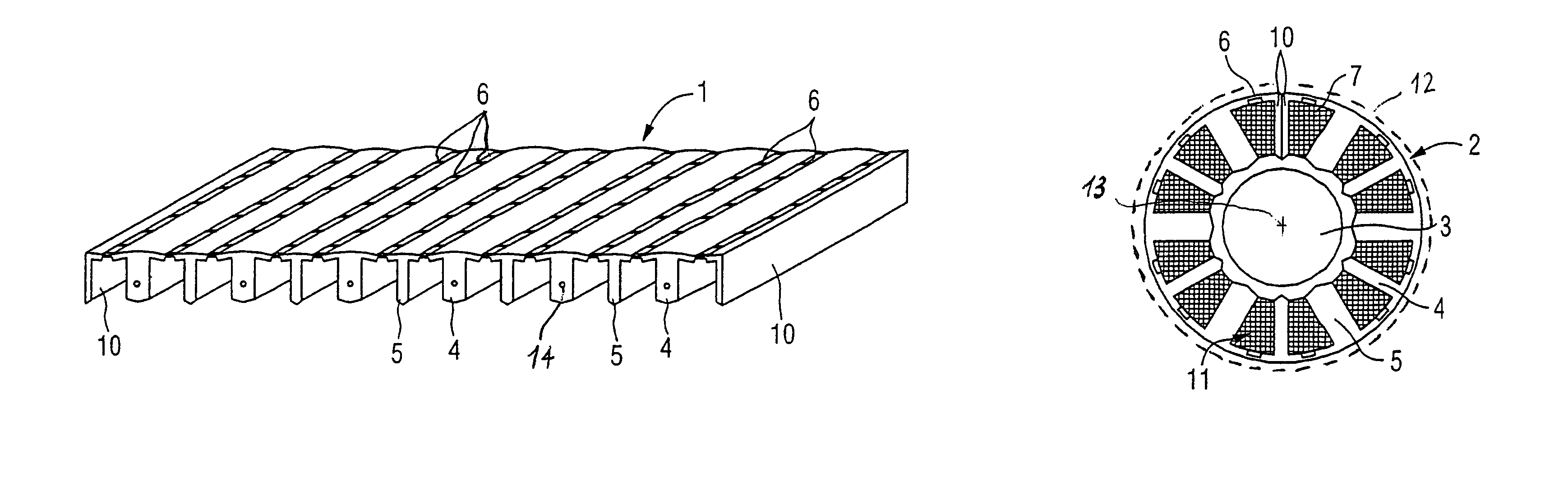
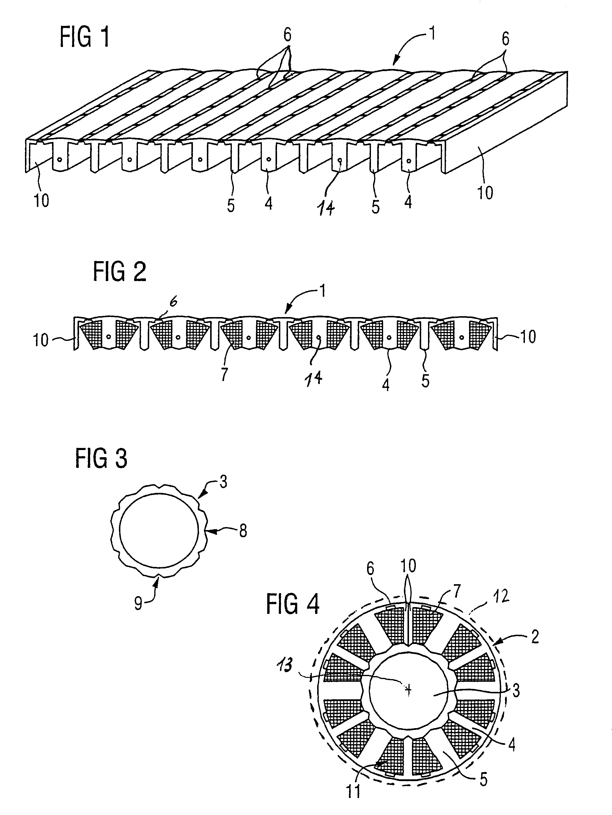
[0021]Turning now to the drawing, and in particular to FIG. 1, there is shown a schematic front, top and side perspective view of one stator potion according to the present invention, generally designated by reference numeral 1 and forming part of a stator, generally designated by reference numeral 2 and shown in more detail in FIG. 4. The stator 2 is the fixed component of an...


PUM


Abstract

An electric machine includes an external rotor rotatable about a rotation axis, and a stator arranged in coaxial relationship to the rotation axis in the external rotor. The stator is comprised of a first stator portion to define a core element, and a second stator portion arranged in the form of a ring in surrounding relationship to the core element and including radially inwardly directed teeth to define a comb-shaped configuration with slots which taper towards the rotation axis for receiving a stator winding. The comb teeth have free ends which are supported on the core element.

Description

CROSS-REFERENCES TO RELATED APPLICATIONS[0001]This application claims the priority of German Patent Application, Serial No. 102 59 090.7, filed Dec. 17, 2002, pursuant to 35 U.S.C. 119(a)–(d), the disclosure of which is incorporated herein by reference.BACKGROUND OF THE INVENTION[0002]The present invention relates, in general, to an electric machine, and to a method of making such an electric machine.[0003]External rotor motors are generally known to have an external rotor which is rotatable about a rotation axis. Disposed in coaxial relationship to the rotation axis inside the external rotor is a stator having slots for receiving the stator winding, whereby the slots taper in a direction to the rotation axis. The stator is formed about its outer circumference with small openings in the slots for wrapping the winding to the stator. In the event, it is desired to fill the slot with winding as much as possible, the winding operation become cumbersome because the stator winding must be...

Claims


Application Information

Patent Timeline
Patent Type & Authority Patents(United States)
IPC IPC(8): H02K1/18H02K1/28H02K1/14
CPCH02K1/148
Inventor HAPPEL, KLAUS
Owner SIEMENS AG
Why Eureka
Try Eureka