Adjustable gaming reel

US20110148037A1Active Publication Date: 2011-06-23SUZOHAPP AMERICAS LLC

Image

  • Adjustable gaming reel
  • Adjustable gaming reel
  • Adjustable gaming reel

Examples


Embodiment Construction

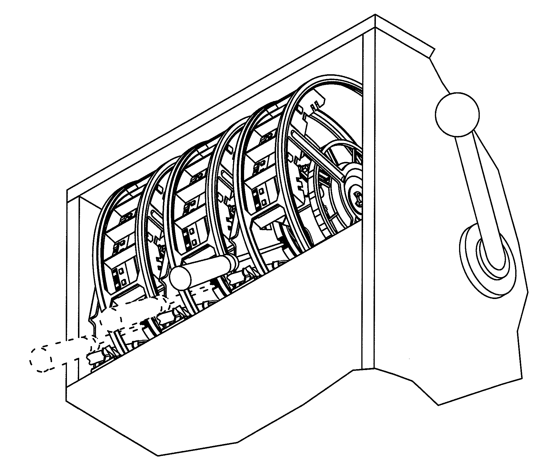
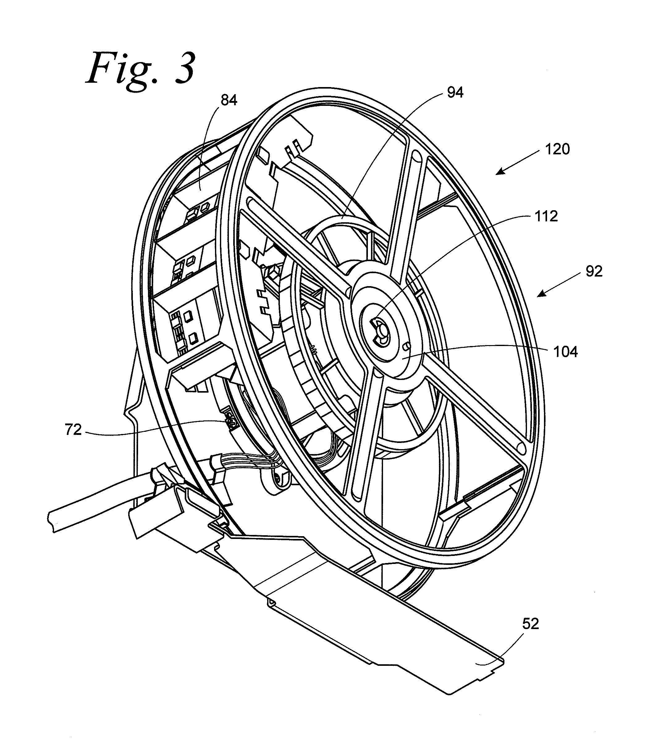
[0032]The present invention relates to a reel assembly for a gaming machine. In accordance with an important aspect of the invention, alignment of the center lines of the symbols can be accomplished without the need to remove the reel assemblies from the gaming machine. The reel assembly includes a two piece motor mount assembly that carries a stepper motor and a lamp assembly. The two piece motor mount assembly includes a fixed mounting ring that is rigidly secured to a fixed reel assembly support and a rotatable mounting ring that is rotatable with respect to the fixed mounting ring. The rotatable mounting ring is interlocked with fixed mounting ring to enable rotation of the rotatable mounting ring, for example, by way of a tongue and groove arrangement with respect to the fixed mounting ring. The lamp assembly is also mounted to the rotatable mounting ring. An adjustment screw for locking the angular position of the fixed mounting ring with respect to the rotatable locking ring ...


PUM


Abstract

A reel assembly for a gaming machine is disclosed. In accordance with an important aspect of the invention, alignment of the center lines of the symbols can be accomplished without the need to remove the reel assemblies from the gaming machine. The reel assembly includes a two piece motor mount assembly that carries a stepper motor and a lamp assembly. The two piece motor mount assembly includes a fixed mounting ring that is rigidly secured to a fixed reel assembly support and a rotatable mounting ring that is rotatable with respect to the fixed mounting ring. The rotatable mounting ring is interlocked with fixed mounting ring to enable rotation of the rotatable mounting ring, for example, by way of a tongue and groove arrangement with respect to the fixed mounting ring. The lamp assembly is also mounted to the rotatable mounting ring. An adjustment screw for locking the angular position of the fixed mounting ring with respect to the rotatable locking ring is accessible along a direction generally accessible while the reel assemblies are installed in the gaming machines. As such, alignment of the symbol center lines can be accomplished without removing the reel assemblies from the gaming machine.

Description

BACKGROUND OF THE INVENTION[0001]1. Field of the Invention[0002]The present invention relates to a reel assembly for a gaming machine and more particularly to a reel assembly for a gaming machine which includes a rotatable reel which carries a strip of symbols and a stepper motor and a lamp device carried by a two piece motor mount assembly configured to enable angular adjustment of the stepper motor with respect to a fixed reel support to facilitate centering of the symbols with the pay lines while the gaming reels remain within the gaming machine[0003]2. Description of the Prior Art[0004]Gaming machines are well known in the art. Such gaming machines are known to include a plurality of reel assemblies. The reel assemblies include a rotatable reel which carries a plastic strip imprinted with symbols. The reel assemblies are rigidly supported in such gaming machines in a side by side relationship such that the axes of rotation of the rotatable reels are essentially horizontal and co...

Claims


Application Information

Patent Timeline
23 Jun 2011
Publication
US20110148037A1
IPC
G07F17/34
CPC
G07F17/3213; G07F17/3202
Inventors
CROSSMAN, COLIN; MCIIRAITH, ADRIAN